
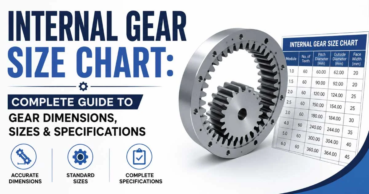
Internal gears play a critical role in modern mechanical systems by delivering smooth power transmission, compact designs, and improved efficiency.
Whether you are an engineer, machinist, student, or gear manufacturer, understanding internal gear dimensions and size charts is essential for selecting the right gear for any application.
This guide explains the fundamentals of internal gear sizing, dimensions, terminology, and selection methods.
What is Internal Gears
Internal gears are cylindrical gears with teeth cut on the inside surface rather than the outside. They usually mesh with external spur gears to provide efficient torque transmission while maintaining compact equipment designs. Their unique structure allows them to operate quietly, making them a preferred choice in planetary gear systems and industrial machinery.
What Is an Internal Gear Size Chart?
An internal gear size chart is a standardized reference table containing important gear dimensions, including module, pitch diameter, outside diameter, root diameter, number of teeth, and pressure angle. Engineers use these charts to ensure compatibility between mating gears while maintaining proper gear ratios and mechanical performance during operation.
Why Internal Gear Size Charts Matter
Selecting an incorrect gear size can lead to poor meshing, excessive wear, vibration, and reduced efficiency. A proper size chart simplifies gear selection by providing standardized measurements that help manufacturers, designers, and maintenance professionals achieve accurate installation and long-lasting performance in various mechanical applications.
Benefits of Using a Size Chart
- Ensures accurate gear selection
- Prevents meshing errors
- Improves transmission efficiency
- Reduces premature wear
- Simplifies manufacturing processes
- Supports standard engineering calculations
Main Components of an Internal Gear Size Chart
Every internal gear size chart includes several dimensions that determine gear compatibility and performance. Understanding these measurements helps engineers calculate proper clearances, tooth engagement, and torque transmission while avoiding common design mistakes that may shorten the lifespan of mechanical systems.
Typical Measurements Include
- Module (m)
- Number of Teeth (Z)
- Pitch Diameter (PD)
- Root Diameter
- Tip Diameter
- Pressure Angle
- Face Width
- Addendum
- Dedendum
Module in Internal Gears Chart
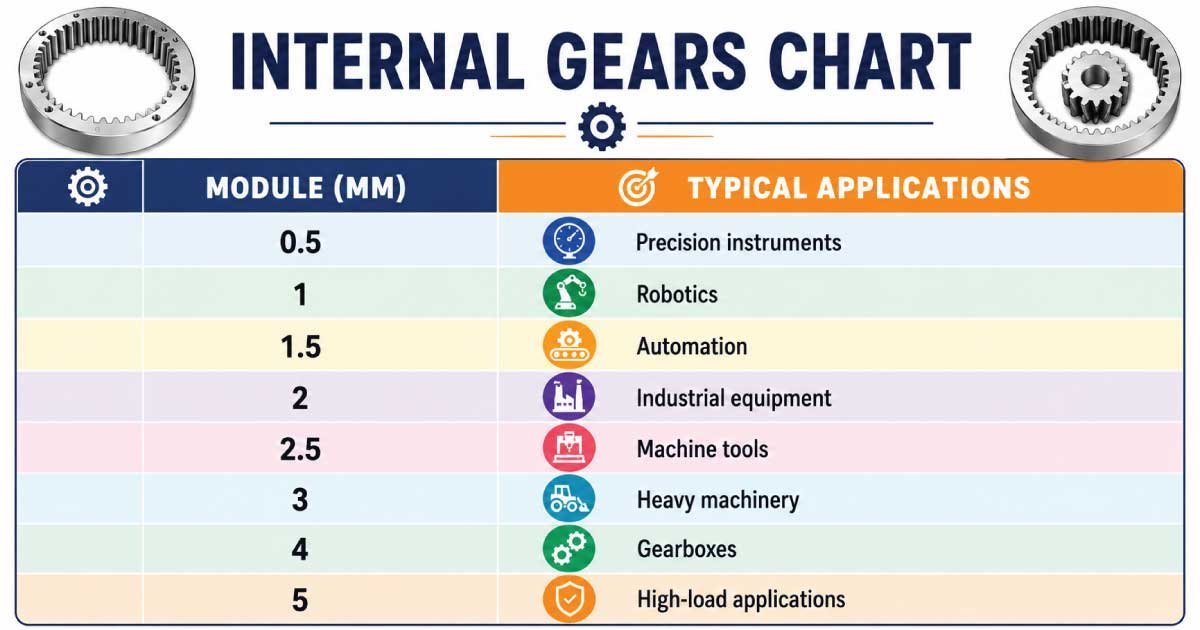
The module is one of the most important measurements in metric gear systems. It represents the size of each gear tooth and directly affects the gear’s strength, load capacity, and compatibility. Two mating gears must always have the same module for proper engagement and smooth operation.
| Module (mm) | Typical Applications |
|---|---|
| 0.5 | Precision instruments |
| 1 | Robotics |
| 1.5 | Automation |
| 2 | Industrial equipment |
| 2.5 | Machine tools |
| 3 | Heavy machinery |
| 4 | Gearboxes |
| 5 | High-load applications |
Internal Gear Size Chart PDF
The Internal Gears Chart provides a quick reference to common gear modules and their typical industrial applications. From precision instruments and robotics to heavy machinery and high-load systems, this chart helps engineers, designers, and technicians choose the appropriate internal gear module for reliable performance and efficient mechanical power transmission.
Number of Teeth Explained
The number of teeth determines the gear ratio, rotational speed, and torque output. Internal gears generally contain more teeth than the external gears they mesh with. Choosing the correct tooth count ensures smooth operation while preventing interference between mating gear teeth during rotation.
Pitch Diameter and Its Importance
Pitch diameter represents the imaginary circle where gear teeth effectively engage. It is one of the primary dimensions used in gear calculations because it influences center distance, speed ratio, and load distribution. Accurate pitch diameter measurements are essential for maintaining reliable gear performance.
Pressure Angle in Internal Gears
The pressure angle affects the direction of force transmission between gear teeth. Standard pressure angles include 20° and 25°, with 20° being the most widely used due to its balance of strength, efficiency, and smooth engagement. Selecting the proper pressure angle enhances durability and reduces operating noise.
Face Width Selection
Face width refers to the width of the gear teeth measured along the gear axis. Wider face widths distribute loads more evenly across the teeth, increasing strength and durability. However, excessively wide gears may increase weight, manufacturing costs, and alignment challenges during installation.
Addendum and Dedendum
The addendum is the height of a tooth above the pitch circle, while the dedendum extends below it toward the root. These dimensions ensure proper tooth engagement and clearance. Balanced addendum and dedendum values minimize interference while maximizing gear strength and operating efficiency.
Standard Internal Gear Size Chart
The following table provides commonly used metric internal gear dimensions.
| Module | Teeth | Pitch Diameter (mm) | Outside Diameter (mm) | Root Diameter (mm) |
|---|---|---|---|---|
| 1 | 20 | 20 | 22 | 17.5 |
| 1 | 30 | 30 | 32 | 27.5 |
| 2 | 20 | 40 | 44 | 35 |
| 2 | 30 | 60 | 64 | 55 |
| 2.5 | 40 | 100 | 105 | 94 |
| 3 | 50 | 150 | 156 | 143 |
| 4 | 60 | 240 | 248 | 232 |
| 5 | 80 | 400 | 410 | 392 |
How to Read an Internal Gear Size Chart
Reading an internal gear size chart begins by identifying the module, followed by the number of teeth. Next, verify the pitch diameter, pressure angle, and face width to ensure compatibility. Finally, compare root and outside diameters to confirm adequate clearance for the intended application.
Quick Reading Steps
- Identify the module.
- Check the tooth count.
- Verify pitch diameter.
- Confirm pressure angle.
- Compare face width.
- Ensure proper clearances.
Common Applications of Internal Gears
Internal gears are widely used in systems requiring compact layouts, high torque transmission, and reliable performance. Their design enables smooth power transfer while reducing vibration and operating noise compared to many alternative gear arrangements.
Industries That Use Internal Gears
- Automotive transmissions
- Planetary gearboxes
- Industrial machinery
- Robotics
- Aerospace systems
- Wind turbines
- Packaging equipment
- Printing machines
- Construction machinery
Factors That Affect Internal Gear Size Selection
Several engineering considerations influence the selection of internal gear sizes. Load capacity, operating speed, available installation space, lubrication, material properties, and manufacturing tolerances all contribute to choosing dimensions that maximize performance, durability, and long-term reliability.
Calculating Internal Gear Dimensions
Accurate gear dimension calculations ensure proper meshing and efficient power transmission. Engineers use standard gear formulas to determine pitch diameter, outside diameter, center distance, and root diameter before manufacturing. These calculations reduce design errors, improve durability, and ensure compatibility between internal and external gears.
Basic Gear Formulas
- Pitch Diameter (PD) = Module × Number of Teeth
- Outside Diameter = Pitch Diameter + (2 × Module)
- Center Distance = (External Gear PD – Internal Gear PD) ÷ 2
- Circular Pitch = π × Module
Metric vs Imperial Internal Gear Sizes
Internal gears are manufactured using both metric and imperial measurement systems. Metric gears use the module system, while imperial gears are based on diametral pitch (DP). Choosing the correct standard ensures compatibility with existing components and prevents costly installation or manufacturing issues.
Comparison Table
| Metric System | Imperial System |
|---|---|
| Module (mm) | Diametral Pitch (DP) |
| Widely used internationally | Common in North America |
| Easier calculations | Traditional engineering standard |
| Preferred for modern designs | Used in legacy equipment |
Materials Used for Internal Gears
The material selected for an internal gear significantly affects its strength, wear resistance, operating life, and cost. Engineers choose materials according to load requirements, environmental conditions, lubrication methods, and manufacturing processes to ensure reliable long-term performance.
Common Materials
- Carbon steel
- Alloy steel
- Stainless steel
- Cast iron
- Bronze
- Brass
- Aluminum alloys
- Engineering plastics
Heat Treatment for Internal Gears
Heat treatment enhances gear durability by increasing hardness and improving resistance to wear and fatigue. Proper treatment extends service life, especially in high-load industrial applications. The chosen process depends on the gear material and expected operating conditions.
Popular Heat Treatment Methods
- Carburizing
- Induction hardening
- Nitriding
- Flame hardening
- Through hardening
- Tempering
Also Read:
Manufacturing Methods for Internal Gears
Internal gears require specialized manufacturing techniques due to their inward-facing teeth. Modern production methods provide exceptional accuracy, smoother tooth profiles, and tighter tolerances, making them suitable for precision machinery and heavy industrial equipment.
Common Manufacturing Processes
- Gear shaping
- Broaching
- CNC machining
- Gear skiving
- Wire EDM
- Gear grinding
Advantages of Internal Gears
Internal gears offer several engineering benefits compared to traditional external gears. Their compact design, smooth engagement, and efficient power transmission make them ideal for high-performance machinery requiring reliable torque transfer in confined spaces.
Key Advantages
- Compact construction
- High torque capacity
- Smooth operation
- Reduced vibration
- Lower operating noise
- Excellent load distribution
- Long service life
- Ideal for planetary gear systems
Also Read:
Limitations of Internal Gears
Despite their advantages, internal gears also present certain challenges. Manufacturing complexity, higher production costs, and inspection difficulties can increase project expenses. Understanding these limitations helps engineers determine whether internal gears are the best solution for specific applications.
Common Limitations
- Higher manufacturing cost
- Complex machining process
- Difficult inspection
- Limited tooling availability
- Requires precise alignment
- Specialized maintenance
Common Design Standards
International gear standards ensure consistent quality, dimensional accuracy, and compatibility between manufacturers. Following recognized standards improves interchangeability while simplifying design, production, and quality control across different industries and global markets.
Widely Used Standards
- ISO Gear Standards
- AGMA Standards
- DIN Standards
- JIS Standards
- ANSI Standards
How to Select the Correct Internal Gear
Choosing the right internal gear involves evaluating several engineering factors beyond size alone. Load requirements, operating speed, lubrication, environmental conditions, material strength, and manufacturing tolerances all influence the final selection for dependable and efficient performance.
Selection Checklist
- Determine module
- Calculate tooth count
- Verify pitch diameter
- Confirm pressure angle
- Check face width
- Choose material
- Verify operating speed
- Evaluate load capacity
- Confirm lubrication method
- Follow industry standards
Also Read:
Common Problems with Incorrect Gear Sizes
Improperly sized internal gears can reduce equipment efficiency and shorten service life. Incorrect dimensions often cause excessive friction, tooth interference, vibration, and overheating, leading to costly repairs and unexpected downtime in industrial operations.
Possible Issues
- Tooth interference
- Gear slipping
- Excessive wear
- Increased vibration
- Noise generation
- Overheating
- Reduced efficiency
- Premature failure
Maintenance Tips for Internal Gears
Routine maintenance keeps internal gears operating efficiently and extends their lifespan. Regular inspections, proper lubrication, alignment verification, and timely replacement of worn components help prevent unexpected failures while maintaining consistent mechanical performance.
Maintenance Best Practices
- Lubricate regularly
- Inspect tooth wear
- Check gear alignment
- Monitor vibration
- Replace damaged gears promptly
- Maintain clean operating conditions
- Inspect bearings
- Verify mounting accuracy
Internal Gear Applications Across Industries
Internal gears are essential in many industries because of their efficiency and compact design. Their ability to transmit high torque with minimal noise makes them suitable for precision equipment as well as heavy-duty industrial machinery operating under demanding conditions.
Major Industries
- Automotive manufacturing
- Aerospace engineering
- Robotics
- Industrial automation
- Mining equipment
- Marine systems
- Wind energy
- Medical equipment
- Packaging machinery
- Food processing equipment
Tips for Reading Manufacturer Gear Charts
Manufacturer gear charts may vary slightly in format, but the core dimensions remain consistent. Always verify the module, tooth count, pressure angle, material specification, and tolerances before purchasing or manufacturing replacement gears to ensure proper fit and reliable performance.
Before Ordering
- Verify module
- Confirm pressure angle
- Match tooth count
- Review dimensional tolerances
- Check material specifications
- Confirm heat treatment
- Compare face width
- Ensure application compatibility
Conclusion
An internal gear size chart is an essential engineering reference for selecting gears that provide reliable, efficient, and long-lasting performance. Understanding important dimensions such as module, pitch diameter, tooth count, pressure angle, and face width helps engineers choose the right gear for specific mechanical applications.
Whether designing new machinery or replacing existing components, accurate gear selection is crucial for achieving smooth operation, proper power transmission, and improved equipment reliability. Using standardized size charts ensures compatibility, reduces the risk of errors, and helps minimize maintenance requirements.
By carefully evaluating gear specifications and application needs, engineers can optimize mechanical performance across a wide range of industrial systems. A properly selected internal gear enhances efficiency, extends component life, and supports dependable operation in demanding environments.
Frequently Asked Questions (FAQs)
What is the purpose of an internal gear size chart?
An internal gear size chart provides standardized dimensions that help engineers and manufacturers select compatible gears for specific applications. It includes important details such as tooth count, module, pressure angle, pitch diameter, and other specifications, ensuring accurate gear meshing, efficient power transmission, and reliable long-term mechanical performance.
What is the most common pressure angle?
The 20-degree pressure angle is the most widely used because it provides an excellent balance between tooth strength, smooth operation, load capacity, and ease of manufacturing. This standard is commonly found in many industrial gear systems due to its reliable performance and compatibility with various mechanical applications.
Can internal gears handle heavy loads?
Yes. Internal gears can handle heavy loads when properly designed with the correct module, material, heat treatment, tooth profile, and face width. These factors determine the gear’s strength and durability, allowing it to transmit high torque efficiently while maintaining reliable operation in demanding industrial environments.
Which industries use internal gears most frequently?
Internal gears are widely used in industries such as automotive, aerospace, robotics, industrial automation, construction equipment, wind energy, marine engineering, and manufacturing. Their compact design, efficient power transmission, and ability to handle high torque make them valuable components in many precision mechanical systems.
How often should internal gears be inspected?
Inspection frequency depends on operating conditions, load levels, speed, and maintenance schedules. Most industrial systems benefit from regular inspections during planned maintenance to identify early signs of wear, alignment problems, lubrication issues, or damaged gear teeth before they lead to costly equipment failures or unexpected downtime.

Engineer Hassan is a Mechanical Engineer with 16+ years of hands-on experience in mechanical hardware, fasteners, and workshop tools. He focuses on size selection, thread identification, and measurement, helping users choose the correct components with accuracy and safety.