
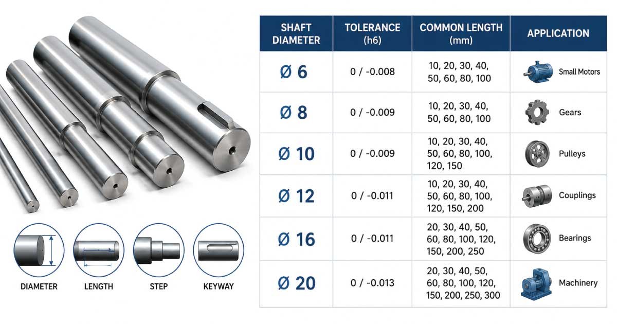
Shafts are among the most critical mechanical components used in machinery, automobiles, industrial equipment, pumps, conveyors, turbines, and manufacturing systems. Choosing the correct shaft size is essential for transmitting torque efficiently, reducing vibration, preventing mechanical failure, and ensuring long service life.
This guide explains shaft dimensions, measurement methods, industry standards, materials, and practical selection factors to help beginners and professionals make informed decisions.
What Is a Shaft?
A shaft is a rotating mechanical element designed to transmit torque and rotational motion from one component to another. It supports gears, pulleys, sprockets, bearings, couplings, and other machine elements while maintaining alignment and strength. Shaft design directly affects machine efficiency, durability, and safety, making proper sizing one of the most important engineering considerations.
In mechanical engineering, shafts are generally manufactured from high-strength metals and precision-machined to achieve accurate diameters and tolerances. Depending on the application, they may include keyways, splines, threads, shoulders, or tapers that improve power transmission and component mounting.
A properly selected shaft provides:
- Reliable torque transmission
- High bending resistance
- Reduced vibration
- Longer bearing life
- Better equipment efficiency
- Lower maintenance costs
Why Shaft Size Matters
Selecting the correct shaft size involves much more than choosing a diameter that fits a bearing or gear. The shaft must safely withstand torsional loads, bending forces, shock loading, and fatigue during continuous operation. An undersized shaft can fail prematurely, while an oversized shaft increases cost, weight, and energy consumption.
Proper shaft sizing helps engineers balance performance, reliability, and manufacturing costs. It also ensures compatibility with bearings, couplings, seals, and power transmission components.
Some major benefits of correct shaft sizing include:
- Improved machine reliability
- Reduced vibration and noise
- Increased power transmission efficiency
- Lower maintenance expenses
- Better fatigue resistance
- Enhanced operational safety
Shaft Size Chart
A shaft size chart provides standard shaft diameters commonly used across industrial machinery. These dimensions simplify component selection because bearings, gears, couplings, and pulleys are manufactured around standardized shaft sizes.
The following table shows commonly available metric shaft diameters.
| Shaft Diameter (mm) | Typical Power Range | Common Applications |
|---|---|---|
| 6 | Very Light | Small electric motors |
| 8 | Light | Fans, hobby equipment |
| 10 | Light | Pumps, small gearboxes |
| 12 | Light | Conveyors |
| 15 | Medium | Industrial drives |
| 20 | Medium | Agricultural machines |
| 25 | Medium | Machine tools |
| 30 | Heavy | Gearboxes |
| 35 | Heavy | Compressors |
| 40 | Heavy | Industrial conveyors |
| 45 | Heavy | Manufacturing equipment |
| 50 | High Load | Large motors |
| 55 | High Load | Crushers |
| 60 | High Load | Heavy-duty machinery |
| 70 | Very Heavy | Mining equipment |
| 80 | Very Heavy | Steel industry |
| 90 | Extreme Load | Rolling mills |
| 100 | Extreme Load | Turbines |
Although these sizes are widely available, engineers always verify torque, bending stress, rotational speed, and bearing compatibility before making a final selection.
Standard Shaft Dimensions
Besides shaft diameter, engineers also specify several additional dimensions that influence machine performance. Understanding these dimensions helps avoid assembly problems and improves overall equipment reliability.
The table below summarizes the most important shaft dimensions.
| Dimension | Description |
|---|---|
| Diameter | Main shaft thickness |
| Length | Total shaft length |
| Keyway Width | Width of key slot |
| Keyway Depth | Depth of key slot |
| Shoulder Diameter | Bearing locating surface |
| Thread Size | End fastening thread |
| Fillet Radius | Reduces stress concentration |
| Journal Diameter | Bearing contact area |
Every dimension plays a role in supporting connected components. For example, fillet radii reduce stress concentration, while shoulders accurately position bearings and gears during assembly.
Types of Shafts
Different machines require different shaft designs depending on speed, loading conditions, and manufacturing requirements. Selecting the appropriate shaft type improves efficiency and reduces maintenance over the equipment’s lifespan.
1. Transmission Shafts
Transmission shafts transfer power between machine components rather than forming part of a single machine. They are commonly found in line shaft systems, conveyors, agricultural equipment, and industrial drives where torque must travel over relatively long distances.
Typical examples include:
- Counter shafts
- Line shafts
- Jack shafts
- Drive shafts
These shafts often support pulleys, sprockets, gears, and couplings.
2. Machine Shafts
Machine shafts are designed specifically for one machine and usually form an integral part of its operation. They are engineered according to machine loads, speed, and component arrangement for maximum performance and durability.
Common examples include:
- Motor shafts
- Pump shafts
- Compressor shafts
- Turbine shafts
- Gearbox shafts
- Spindle shafts
3. Solid Shafts
Solid shafts are manufactured from a single solid bar of steel or other metal. They offer excellent strength, simple manufacturing, and high resistance to bending, making them the preferred choice for most industrial machinery.
Advantages include:
- High strength
- Easy machining
- Lower manufacturing complexity
- Excellent fatigue resistance
- Reliable long-term performance
4. Hollow Shafts
Hollow shafts contain an internal bore that reduces weight while maintaining excellent torsional strength. They are widely used in aerospace, robotics, automotive engineering, and high-speed machinery where reducing rotating mass improves efficiency.
Compared with solid shafts, hollow shafts typically provide:
- Lower weight
- Better power-to-weight ratio
- Reduced rotational inertia
- Improved dynamic response
Common Shaft Materials
Material selection has a major influence on shaft strength, corrosion resistance, fatigue life, and manufacturing cost. Engineers choose materials based on load, operating environment, rotational speed, and maintenance requirements.
The following comparison highlights commonly used shaft materials.
| Material | Strength | Corrosion Resistance | Common Uses |
|---|---|---|---|
| Carbon Steel | High | Moderate | General machinery |
| Alloy Steel | Very High | Moderate | Heavy equipment |
| Stainless Steel | High | Excellent | Food processing |
| Tool Steel | Extremely High | Moderate | Precision equipment |
| Aluminum Alloy | Medium | Good | Lightweight systems |
| Titanium Alloy | Very High | Excellent | Aerospace |
Carbon steel remains the most economical option for general industrial applications, while alloy steel is preferred for heavy-duty equipment requiring greater fatigue strength. Stainless steel is widely selected for marine, pharmaceutical, and food-processing environments due to its superior corrosion resistance.
👉 Whether you’re replacing or installing a component, our Wing Nut size chart offers an Expert Guide and Professional Guide to make the right selection with confidence.
Industry Standards
International standards help manufacturers produce interchangeable shafts that fit bearings, gears, couplings, and other machine components consistently. Following recognized standards improves compatibility, simplifies maintenance, and reduces engineering errors during equipment design.
Some of the most commonly referenced shaft standards include:
| Standard | Purpose |
|---|---|
| ISO | International dimensional standards |
| ANSI | American engineering standards |
| DIN | German industrial specifications |
| BS | British standards |
| JIS | Japanese industrial standards |
| AGMA | Gear and power transmission standards |
Engineers often combine several standards when designing complete power transmission systems, especially for equipment intended for global markets.
How to Measure Shaft Size
Accurate shaft measurement is essential before replacing bearings, couplings, gears, seals, or pulleys. Even a small measurement error can result in poor component fit, excessive vibration, premature wear, or assembly failure.
Before measuring, clean the shaft thoroughly to remove grease, rust, dirt, or burrs. Always use calibrated measuring tools for reliable results.
1. Tools Required
Several precision instruments are commonly used to measure shaft dimensions. The choice depends on the required accuracy and shaft size.
Recommended tools include:
- Vernier caliper
- Outside micrometer
- Steel ruler
- Dial indicator
- Digital caliper
- Surface gauge
Digital measuring instruments provide faster readings, while micrometers offer the highest precision for critical industrial applications.
2. Measurement Steps
Following a systematic procedure improves accuracy and ensures repeatable measurements. Engineers often measure multiple locations to detect wear or taper before selecting replacement components.
Basic measurement procedure:
- Clean the shaft surface.
- Measure the outside diameter.
- Measure several locations.
- Record the largest and smallest values.
- Measure shaft length.
- Check keyway dimensions.
- Inspect shoulders and threaded ends.
- Verify tolerances against manufacturer specifications.
Measuring at several points helps identify uneven wear that may not be visible during a quick inspection.
Understanding Shaft Tolerances
Manufacturing tolerances determine how accurately a shaft matches bearings, hubs, and other mating components. Even when two shafts share the same nominal diameter, different tolerance classes produce different fits.
Common shaft fits include clearance fits, transition fits, and interference fits. Clearance fits allow easy assembly, transition fits provide moderate holding force, and interference fits create a tight connection that prevents movement under heavy loads.
Choosing the correct tolerance depends on rotational speed, transmitted torque, temperature changes, and maintenance requirements. Engineers always match shaft tolerances with bearing and hub specifications to ensure reliable operation without excessive wear.
Shaft Size Selection Guide
Selecting the correct shaft size requires more than matching a diameter with a bearing or coupling. Engineers evaluate transmitted power, rotational speed, bending loads, material properties, operating environment, and expected service life. A well-sized shaft improves efficiency, reduces maintenance, and minimizes the risk of fatigue failure during continuous operation.
When selecting a shaft, consider the following factors:
- Required torque and power transmission
- Rotational speed (RPM)
- Bending and shock loads
- Shaft material strength
- Bearing compatibility
- Environmental conditions
- Manufacturing cost
- Future maintenance requirements
For example, a conveyor operating continuously in a mining facility requires a larger and stronger shaft than a small electric motor used in a workshop. Considering the entire operating system rather than only the shaft diameter leads to better long-term performance.
👉 Explore our detailed Hex Nut size chart for accurate specifications, an Expert Guide, and a Professional Guide that helps you avoid common sizing mistakes.
Basic Shaft Design Formula
Engineers use mathematical formulas to estimate the minimum shaft diameter before performing detailed stress analysis. These calculations provide a starting point for selecting standard shaft sizes and are especially useful during preliminary machine design.
One commonly used torsion formula for a solid circular shaft is:
Torque (T) = (π × τ × d³) / 16
Where:
- T = Torque (N·mm)
- τ = Allowable shear stress (MPa)
- d = Shaft diameter (mm)
- π = 3.1416
Rearranging the formula allows engineers to calculate the required shaft diameter based on the expected torque and allowable material stress. Final designs also account for bending stress, stress concentration, shock loading, and safety factors.
Example Calculation
Suppose a shaft must transmit 600 N·m of torque using medium carbon steel with an allowable shear stress of 40 MPa.
After converting the torque to 600,000 N·mm, the design equation indicates a shaft diameter close to 42 mm. In practice, engineers would typically choose the next standard size, such as 45 mm, to provide an additional safety margin and improve component compatibility.
Common Shaft Applications
Shafts are used in almost every rotating machine across industrial, commercial, and transportation sectors. Their primary purpose is to transmit power while supporting rotating components with minimal deflection and vibration.
Some of the most common applications include:
- Electric motors
- Industrial gearboxes
- Centrifugal pumps
- Compressors
- Conveyor systems
- Agricultural machinery
- Wind turbines
- Automotive transmissions
In each application, shaft dimensions are selected according to operating speed, transmitted power, expected lifespan, and environmental conditions. High-speed machinery often requires tighter tolerances and better surface finishes than low-speed equipment.
Advantages of Proper Shaft Sizing
Choosing the correct shaft dimensions provides significant mechanical and economic benefits throughout the equipment’s service life. Proper sizing reduces unexpected failures and improves the performance of connected machine elements.
Major advantages include:
- Improved power transmission efficiency
- Longer bearing life
- Lower vibration levels
- Reduced shaft deflection
- Better fatigue resistance
- Increased machine reliability
- Lower maintenance costs
- Enhanced operational safety
Although larger shafts generally provide greater strength, unnecessarily increasing the diameter adds weight, increases manufacturing costs, and may require larger bearings and couplings. Selecting the optimal size achieves the best balance between performance and cost.
Disadvantages of Incorrect Shaft Sizing
Improper shaft sizing is one of the leading causes of mechanical failures in rotating equipment. Both undersized and oversized shafts create operational problems that affect reliability and efficiency.
An undersized shaft may experience excessive torsional stress, bending, and fatigue cracking. Over time, this can lead to sudden failure, bearing damage, and costly downtime. Conversely, an oversized shaft increases material costs, rotational inertia, and overall machine weight without providing proportional benefits.
Recognizing these risks during the design stage helps engineers avoid expensive repairs and production interruptions.
Common Shaft Problems
Even properly designed shafts can develop issues because of poor installation, overload conditions, lubrication failures, or long-term wear. Identifying these problems early helps prevent secondary damage to bearings, gears, and couplings.
Common shaft problems include:
- Excessive vibration
- Shaft bending
- Fatigue cracks
- Surface wear
- Corrosion
- Misalignment
- Keyway damage
- Bearing journal wear
Regular inspections and vibration monitoring often detect these problems before complete mechanical failure occurs.
👉 For trusted dimensions and professional recommendations, visit our complete Flange Nut size chart, where every article includes an Expert Guide and Professional Guide for better decision-making.
Common Selection Mistakes
Many shaft failures occur because the initial design overlooked important operating conditions. Avoiding common selection mistakes improves machine reliability and reduces maintenance expenses.
Some of the most frequent mistakes are:
- Choosing diameter based only on available space
- Ignoring bending loads
- Underestimating shock loading
- Selecting unsuitable materials
- Overlooking corrosion resistance
- Using incorrect tolerances
- Ignoring bearing compatibility
- Skipping safety factor calculations
Engineers should always evaluate the complete operating environment rather than relying solely on catalog dimensions.
Maintenance Tips
Proper maintenance significantly extends shaft life and prevents unexpected breakdowns. Regular inspections also improve the reliability of connected components such as bearings, gears, seals, and couplings.
Recommended maintenance practices include:
- Inspect shafts regularly for wear
- Monitor vibration levels
- Lubricate bearings correctly
- Check shaft alignment
- Replace damaged keys promptly
- Protect against corrosion
- Measure journal wear periodically
- Balance rotating assemblies after repairs
Preventive maintenance is generally far less expensive than repairing equipment after a shaft failure.
Troubleshooting Shaft Issues
When machinery begins producing abnormal noise, vibration, or excessive heat, the shaft should be included in the inspection process. A systematic troubleshooting approach helps identify the root cause rather than simply replacing damaged components.
| Problem | Possible Cause | Recommended Solution |
|---|---|---|
| High vibration | Misalignment | Realign shaft and coupling |
| Bearing overheating | Incorrect shaft fit | Verify tolerances |
| Shaft cracking | Fatigue loading | Replace shaft and review design |
| Excessive wear | Poor lubrication | Improve lubrication schedule |
| Noise during operation | Bent shaft | Measure runout and replace if required |
| Coupling failure | Improper shaft size | Confirm diameter compatibility |
Addressing the underlying cause rather than the symptom helps prevent repeated failures and extends equipment life.
Buying Guide
Purchasing the right shaft requires evaluating more than just diameter and length. A high-quality shaft should meet applicable standards, provide the required mechanical properties, and suit the intended operating conditions.
Before purchasing, verify:
- Shaft diameter and length
- Material grade
- Surface finish
- Heat treatment
- Dimensional tolerances
- Keyway or spline dimensions
- Compliance with relevant standards
- Manufacturer quality certifications
Buying from reputable manufacturers ensures consistent machining accuracy, traceable materials, and dependable long-term performance.
Conclusion
Choosing the correct shaft size chart is essential for designing reliable and efficient mechanical systems. The proper shaft diameter, material, tolerance, and dimensions ensure safe torque transmission, minimize vibration, extend bearing life, and reduce maintenance costs.
Understanding industry standards, measurement techniques, design formulas, and material selection enables engineers, technicians, mechanics, and DIY users to make informed decisions for a wide range of applications. By following best practices, performing accurate calculations, and selecting high-quality components, you can improve equipment performance, prevent premature failures, and maximize the service life of your machinery.
Whether you are replacing an existing shaft or designing a new power transmission system, using a comprehensive shaft size chart provides a strong foundation for dependable and cost-effective operation.
Frequently Asked Questions
What is the standard shaft size?
There is no single standard shaft size because the correct diameter depends on torque, speed, bending loads, and application requirements. However, common metric shaft diameters include 10 mm, 12 mm, 20 mm, 25 mm, 30 mm, 40 mm, 50 mm, and 60 mm. Engineers usually select the nearest standard size after completing design calculations and checking compatibility with bearings, gears, and couplings.
How do I measure shaft diameter accurately?
The most accurate method is to use an outside micrometer or a calibrated digital vernier caliper. Measure the shaft at several locations around the circumference and along its length to detect wear, taper, or out-of-round conditions. Always clean the shaft before measuring and compare the results with the manufacturer’s specified tolerances.
Which material is best for machine shafts?
The ideal material depends on the operating conditions. Carbon steel is suitable for many general-purpose applications because it offers good strength at a reasonable cost. Alloy steel provides higher fatigue resistance for heavy-duty machinery, while stainless steel is preferred in corrosive environments such as food processing, marine equipment, and chemical plants.
Why is shaft tolerance important?
Tolerance determines how tightly the shaft fits with bearings, gears, hubs, and couplings. Incorrect tolerances may cause excessive vibration, premature wear, overheating, or difficult assembly. Choosing the appropriate clearance, transition, or interference fit ensures reliable operation, proper load distribution, and longer component life.
Can a larger shaft always improve performance?
Not necessarily. While a larger shaft generally increases strength, it also adds weight, rotational inertia, material cost, and may require larger supporting components. Oversizing can reduce efficiency in certain applications. Engineers aim to select the smallest shaft that safely withstands all operating loads while meeting performance and reliability requirements.
How often should shafts be inspected?
Inspection frequency depends on the operating environment and equipment duty cycle. Machines operating under heavy loads, high speeds, or continuous service should be inspected more frequently than lightly loaded equipment. Routine checks should include alignment, vibration, lubrication, surface wear, bearing journals, and signs of corrosion or fatigue cracking to identify issues before failure occurs.

Engineer Hassan is a Mechanical Engineer with 16+ years of hands-on experience in mechanical hardware, fasteners, and workshop tools. He focuses on size selection, thread identification, and measurement, helping users choose the correct components with accuracy and safety.