
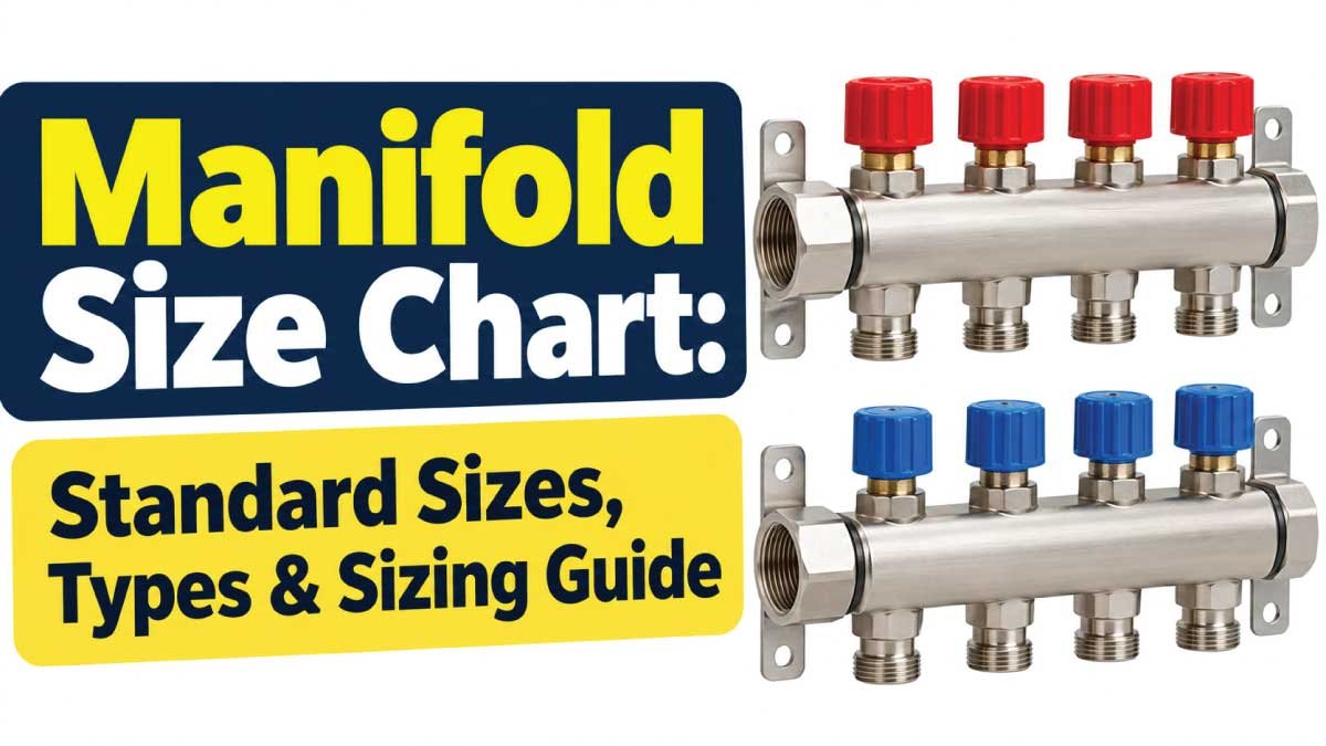
Manifolds are used in many systems to distribute, collect, isolate, or control fluid flow, but there is no single universal manifold size chart that applies to every application. A hydraulic manifold is sized differently from a radiant-heating manifold, plumbing manifold, or pneumatic manifold.
This guide explains the most important manifold dimensions, port sizes, outlet counts, manifold types, and sizing considerations. It also shows representative manufacturer specifications so you can understand how manifold sizing works without treating one product’s dimensions as a universal standard.
What Is a Manifold?
A manifold is a component that connects one supply or return path to multiple branches. Depending on the application, it may divide incoming fluid into several circuits, combine multiple flows into one line, or provide individual control over each branch.
Manifolds are commonly found in:
- Hydraulic power systems
- Pneumatic systems
- Plumbing distribution
- Radiant floor heating
- Hydronic heating and cooling
- Irrigation systems
- Process piping
- Instrumentation
- Refrigeration and HVAC equipment
- Industrial fluid-control systems
A manifold may be a simple metal header with several outlets or a machined block containing internal passages, valves, cartridge cavities, sensors, and mounting provisions.
The correct manifold size depends on more than the nominal pipe or tube diameter. Flow rate, pressure, number of branches, connection standard, fluid type, temperature, pressure drop, and available installation space all affect selection.
Manifold Size Chart: Common Port and Outlet Sizes
Because manifold dimensions vary substantially by application and manufacturer, the following chart is best treated as a reference to common sizing ranges, not a universal dimensional standard.
| Manifold Feature | Common Sizes / Configurations | Typical Application |
|---|---|---|
| Main connection | 1/2″, 3/4″, 1″, 1-1/4″, 1-1/2″, 2″ | Plumbing, hydronic |
| Hydraulic ports | 1/4″, 3/8″, 1/2″, 3/4″, 1″ | Hydraulic systems |
| Hydraulic SAE ports | SAE-4 to SAE-16 | Mobile/industrial hydraulics |
| NPT ports | 1/8″ to 1″ and larger | Hydraulic/process systems |
| BSPP ports | G1/8″ to G1″ and larger | International fluid systems |
| Metric ports | M5 to M33 examples | Metric hydraulic systems |
| Outlet count | 2, 4, 6, 8 or more | Distribution systems |
| Valve stations | D03 to D10 examples | Hydraulic valve manifolds |
| Hydronic manifold size | 1″, 1-1/4″, 1-1/2″, 2″ examples | Heating/cooling |
| Outlet spacing | Application-specific | Plumbing/hydronic |
| Body material | Brass, steel, stainless steel, aluminum, polymer | Varies by service |
For example, hydraulic manifold products can use SAE, NPT, BSPP, or metric connections, while hydronic products may use larger threaded connections and multiple loop outlets. Manufacturer documentation should therefore be used for the final selection.
How Manifold Size Is Specified
A manifold can have several different measurements, and confusing them is a common source of sizing errors.
Port Size
Port size identifies the connection used for the inlet, outlet, or branch connection. Depending on the manifold, this may be expressed as:
- Nominal pipe size
- NPT size
- BSPP/G size
- SAE dash size
- Metric thread size
- Tube connection size
A 1/2-inch port, for example, does not necessarily mean that the manifold body has a 1/2-inch outside diameter.
Thread designation and actual physical dimensions are different measurements.
Number of Outlets
Outlet count describes how many branch circuits can connect to the manifold.
Common configurations include:
- 2 outlets
- 3 outlets
- 4 outlets
- 6 outlets
- 8 outlets
- Higher outlet counts for specialized distribution systems
Some hydraulic manufacturers offer standard manifolds with 2, 4, 6, or 8 outlets.
Body Dimensions
For a block manifold, overall dimensions may be listed as:
Length × Width × Height
For a bar-style manifold, manufacturers may instead provide:
- Overall length
- Body diameter or width
- Outlet center-to-center distance
- Mounting-hole spacing
- Inlet location
- Outlet orientation
These dimensions are particularly important when replacing an existing manifold.
Types of Manifolds and Their Size Requirements
Manifold sizing becomes much easier when the application is identified first.
Hydraulic Manifolds
Hydraulic manifolds route pressurized hydraulic fluid between pumps, valves, actuators, and other components.
They can be:
- Single-function blocks
- Multi-station manifolds
- Cartridge valve manifolds
- Subplates
- Modular manifolds
- Custom drilled manifold blocks
Hydraulic manifold size is strongly influenced by flow rate and working pressure. A small port may physically connect to a system but still create excessive pressure loss if the required flow is too high.
Some standard hydraulic manifold ranges use D03 through D10 valve sizes, while other products use SAE, NPT, BSPP, or metric ports.
Hydronic Manifolds
Hydronic manifolds distribute hot or chilled water to multiple heating or cooling circuits.
They are common in:
- Radiant floor heating
- Radiant wall heating
- Chilled-water systems
- Heating zones
- Cooling circuits
Hydronic manifold sizing is usually associated with main connection size, loop count, branch connection size, and required flow.
For example, Uponor lists manifold assemblies in 1-inch and 1-1/4-inch sizes for certain commercial and residential radiant applications.
Plumbing Manifolds
Plumbing manifolds distribute water from a central location to several fixtures.
They may serve:
- Sinks
- Showers
- Toilets
- Washing machines
- Dishwashers
- Other dedicated water lines
The manifold must accommodate the required number of branches while maintaining adequate supply pressure and flow.
Pneumatic Manifolds
Pneumatic manifolds distribute compressed air to multiple valves or circuits.
Important specifications include:
- Port size
- Number of valve stations
- Airflow
- Operating pressure
- Valve interface
- Mounting arrangement
Pneumatic manifold sizing is therefore more than simply matching the hose diameter.
Instrumentation Manifolds
Instrumentation manifolds are commonly used with pressure instruments and differential-pressure applications.
Typical configurations include:
- 2-valve manifolds
- 3-valve manifolds
- 5-valve manifolds
Their dimensions and connection sizes are usually selected according to the instrument, process connection, pressure rating, and installation requirements.
Hydraulic Manifold Size Chart
Hydraulic manifolds deserve separate consideration because pressure and flow can vary dramatically between systems.
The following table provides examples of commonly encountered port designations rather than a universal flow rating.
| Nominal Port | Example SAE Dash Size | Example Metric Connection | Common Use |
|---|---|---|---|
| 1/4″ | SAE-4 | M10 × 1 | Small hydraulic circuits |
| 3/8″ | SAE-6 | — | General hydraulic circuits |
| 1/2″ | SAE-8 | M16 × 1.5 | Medium-flow circuits |
| 3/4″ | SAE-12 | M22 × 1.5 | Higher-flow circuits |
| 1″ | SAE-16 | — | High-flow hydraulic circuits |
Actual flow capacity depends on the internal passage, port geometry, manifold material, allowable pressure drop, and manufacturer design.
One manufacturer, for example, lists SAE-4 through SAE-16 connections and provides different flow and pressure ratings for those port configurations.
Hydraulic Valve Manifold Sizes
Hydraulic valve manifolds may also be identified by standardized valve mounting sizes rather than simply by pipe-thread diameter.
For example, Hyvair manufactures manifolds and subplates from D03 through D10, while its D03 and D05 products are offered in industry-standard configurations.
This distinction matters because a valve interface size and a pipe connection size describe different characteristics.
Hydronic Manifold Size Chart
Hydronic systems often use manifold body sizes based on the number of circuits and total required flow.
| Manifold Category | Representative Main Size | Typical Configuration |
|---|---|---|
| Small hydronic manifold | 1″ | Residential/small zones |
| Medium hydronic manifold | 1-1/4″ | Multiple circuits |
| Large hydronic manifold | 1-1/2″ | Higher-flow distribution |
| Commercial manifold | 2″ or larger | Larger systems |
These are representative categories, not universal sizing rules.
For example, Uponor lists commercial stainless-steel manifold assemblies using 1-1/2-inch distribution connections and 1-inch isolation connections, while certain larger assemblies use 1-1/4-inch connections.
Caleffi also provides heating and cooling manifolds with different main and outlet connection arrangements. One four-outlet model, for example, uses a 2-inch main connection and 1-1/2-inch outlet connections, with 125 mm outlet center spacing.
Manifold Outlet Count and Spacing
The number of outlets is one of the most visible differences between manifold sizes.
A two-outlet manifold is compact and suitable for a small number of circuits, while larger manifolds may accommodate six, eight, ten, or more connections.
However, outlet count alone does not determine capacity.
A manifold with eight small outlets may have a very different flow capability from an eight-outlet manifold designed for large hydronic circuits.
Outlet Center-to-Center Distance
Outlet spacing is especially important during installation.
The center-to-center measurement determines:
- How closely pipes can be installed
- Whether fittings will interfere
- Required cabinet width
- Valve accessibility
- Insulation clearance
- Service access
Some hydronic products use standardized outlet spacing within a product family. Caleffi, for example, lists 125 mm center-to-center spacing on several of its heating and cooling manifold products.
Always verify the manufacturer’s dimensional drawing before preparing mounting holes or pipe runs.
How to Choose the Correct Manifold Size
Selecting a manifold should begin with the system requirements rather than the physical pipe size alone.
1. Determine the Required Flow Rate
Flow is one of the most important sizing inputs.
For hydraulic systems, flow may be expressed in:
- GPM
- L/min
- L/s
For hydronic systems, you may also encounter:
- GPM
- m³/h
- L/min
The manifold should provide sufficient internal passage area without creating unacceptable pressure loss.
2. Determine Working Pressure
The manifold must be rated for the system’s maximum operating pressure.
Consider:
- Normal working pressure
- Maximum operating pressure
- Pressure spikes
- Temperature effects
- Proof-test requirements
- Safety margin specified by the manufacturer
Never assume that two manifolds with identical port sizes have identical pressure ratings.
For example, hydraulic manifold products can have pressure ratings that vary significantly with material, configuration, and port arrangement.
3. Count the Required Branches
Determine how many separate circuits are required.
For a hydronic installation, count the heating or cooling loops. For hydraulic equipment, count the required valve or actuator circuits.
Allowing for future expansion can sometimes be useful, but unused outlets should be handled according to the manufacturer’s instructions.
4. Match the Connection Standard
Do not select a manifold solely by nominal diameter.
Confirm whether the system requires:
- NPT
- BSPP/G
- SAE O-ring boss
- ORFS
- Metric threads
- Compression connections
- Push-to-connect fittings
- Flanged connections
Thread standards that appear similar may not be interchangeable.
5. Check Pressure Drop
The manifold should not become an unnecessary restriction.
An undersized internal passage can increase velocity and pressure loss. This is particularly important in high-flow hydraulic and hydronic systems.
A manifold-sizing approach should therefore consider the flow path, branch flow, and acceptable pressure drop rather than simply matching the inlet pipe diameter.
Also Read:
Manifold Dimensions You Should Check
Before ordering a replacement or new manifold, record all important dimensions.
| Dimension | Why It Matters |
|---|---|
| Overall length | Confirms available installation space |
| Overall width | Determines cabinet or mounting clearance |
| Overall height | Prevents interference |
| Main inlet size | Matches supply connection |
| Outlet size | Matches branch piping |
| Outlet count | Determines number of circuits |
| Outlet spacing | Prevents fitting interference |
| Mounting-hole spacing | Ensures proper installation |
| Thread type | Prevents incompatible connections |
| Port orientation | Determines pipe routing |
| Valve clearance | Allows operation and maintenance |
A product catalog may provide only some of these measurements, so consult the manufacturer’s dimensional drawing when exact fit is required.
How to Measure a Manifold
If you are replacing an existing manifold, measuring the old component can help identify a compatible product.
Step 1: Measure the Overall Body
Measure:
- Length
- Width
- Height
- Body diameter if cylindrical
Use a caliper where greater accuracy is required.
Step 2: Identify the Inlet and Outlet Connections
Determine the connection type rather than guessing from its apparent diameter.
Look for markings such as:
- NPT
- BSP
- SAE
- G
- Metric thread designation
- Manufacturer part number
Thread identification is more reliable than measuring the outside diameter and assuming the nominal size.
Step 3: Count the Outlets
Record the total number of branch connections.
Also note whether the outlets are:
- All on one side
- Opposing
- Alternating
- Angled
- Independently valved
Step 4: Measure Outlet Spacing
Measure from the center of one outlet to the center of the next.
Record the distance in millimeters or inches and use the same unit throughout your measurements.
Step 5: Record Mounting Dimensions
Measure:
- Mounting-hole diameter
- Hole-to-hole spacing
- Bracket dimensions
- Mounting orientation
These details can determine whether a replacement is actually compatible.
Also Read:
Manifold Materials and Their Effect on Selection
Manifold material should match the pressure, temperature, fluid, corrosion environment, and weight requirements.
Brass
Brass is widely used in plumbing and hydronic applications because it offers useful corrosion resistance and is compatible with many water-distribution applications.
Stainless Steel
Stainless steel is often selected where corrosion resistance, cleanliness, or demanding environmental conditions are important.
Aluminum
Aluminum can provide a lightweight option for hydraulic manifold blocks.
Some manufacturers offer 6061-T6 aluminum manifold blocks alongside steel and stainless-steel alternatives.
Steel
Steel is commonly used where strength, pressure capability, and durability are important.
Material selection should always be based on the actual service conditions rather than assuming that one material is universally better.
Also Read:
Common Manifold Sizing Mistakes
Even when the port size looks correct, a manifold can still be unsuitable.
Choosing Only by Pipe Diameter
Matching the manifold’s nominal connection to the existing pipe is not enough.
Flow rate, pressure drop, internal passages, and branch requirements must also be considered.
Ignoring Thread Standards
A 1/2-inch NPT connection is not automatically interchangeable with every 1/2-inch connection.
Confirm the exact thread specification.
Ignoring Outlet Spacing
A manifold may have the correct port count but still fail to fit because the outlet spacing or overall body dimensions are different.
Ignoring Flow Distribution
The main passage must support the combined requirements of the connected branches.
For parallel circuits, manifold design affects how effectively flow is distributed among those circuits.
Using a Product Rating as a Universal Standard
A manufacturer’s listed flow or pressure rating belongs to that particular product configuration.
It should not automatically be applied to another manufacturer’s manifold.
Manifold Size vs Pipe Size
Manifold size and pipe size are related, but they are not identical.
A manifold may have:
- A larger inlet than its branch outlets
- Different inlet and outlet standards
- Internal passages larger or smaller than the nominal connection
- Multiple branch sizes
- Integrated valves or flow meters
For example, a hydronic manifold can have a relatively large main connection while using smaller individual loop connections. This allows multiple circuits to be supplied from a common header.
The correct approach is to size the manifold around total system flow and branch requirements, then verify connection compatibility.
Example Manifold Sizing Approach
Suppose a hydronic system has several heating circuits.
Start by determining:
- Required flow for each circuit.
- Total flow through the manifold.
- Number of outlets.
- Required main connection.
- Branch connection size.
- Maximum acceptable pressure drop.
- Operating temperature.
- Maximum system pressure.
- Available installation space.
- Required valve and balancing equipment.
If a manufacturer provides a manifold with a specified maximum recommended flow, use that documented value rather than estimating capacity from the pipe diameter alone.
For example, Caleffi publishes specific flow and pressure information for individual manifold products, while Uponor provides connection and loop-specific details for its manifold assemblies.
Manifold Sizing for Hydraulic Systems
Hydraulic applications require additional attention because pressures can be much higher than typical water-distribution systems.
When selecting a hydraulic manifold, check:
- Maximum working pressure
- Required flow rate
- Internal passage diameter
- Port size
- Valve cavity or mounting interface
- Material
- Fluid compatibility
- Temperature
- Pressure-drop requirements
- Mounting arrangement
- Service access
A hydraulic manifold may also integrate cartridge valves, relief functions, check valves, flow controls, pressure controls, and sensor ports.
For example, standard hydraulic manifolds are available with different valve stations and connection sizes, while specialized manifold blocks can combine multiple functions into one machined body.
Manifold Sizing for Heating and Cooling
For hydronic applications, sizing should account for both the main distribution flow and individual circuit flow.
Important factors include:
- Number of loops
- Flow per loop
- Total flow
- Supply and return temperature
- Pressure drop
- Main connection size
- Branch connection size
- Flow meters
- Isolation valves
- Balancing valves
- Cabinet dimensions
Some commercial hydronic manifolds incorporate flow meters and isolation valves, allowing individual circuits to be isolated and balanced.
The manifold should therefore be treated as part of the complete hydronic distribution system rather than as an isolated fitting.
Frequently Asked Questions
What are the most common manifold sizes?
Common connection sizes include 1/2, 3/4, 1, 1-1/4, 1-1/2, and 2 inches in many plumbing and hydronic applications. Hydraulic manifolds can use smaller SAE, NPT, BSPP, and metric connections. The actual available sizes depend on the application and manufacturer.
How many outlets can a manifold have?
Manifolds may have two, four, six, eight, or many more outlets. Hydraulic products commonly offer several standard outlet configurations, while hydronic manifolds may be selected according to the number of heating or cooling loops.
Does a larger manifold always provide more flow?
No. A larger nominal connection does not automatically guarantee greater usable flow. Internal passage dimensions, configuration, fluid properties, pressure drop, and manufacturer ratings all influence actual capacity.
How do I know what manifold size I need?
Start with the required flow rate, operating pressure, number of branches, connection type, acceptable pressure drop, and physical installation space. Then compare those requirements with the manufacturer’s specifications.
Can I replace a manifold with the same port size?
Not necessarily. The replacement should also match the connection standard, outlet count, spacing, mounting dimensions, pressure rating, flow requirements, material compatibility, and port orientation.
What is the difference between a manifold and a header?
The terms can overlap. A header generally refers to a pipe or chamber that distributes or collects flow, while a manifold often describes a more integrated distribution or control component. In practical applications, manufacturers may use the terms differently.
How to Read a Manifold Size Chart
When reviewing a manufacturer’s manifold size chart, do not focus only on the first dimension.
Check the complete specification:
- Port size — identifies the connection.
- Outlet count — identifies the number of branches.
- Flow rating — indicates the intended flow capacity.
- Pressure rating — establishes allowable working pressure.
- Dimensions — confirm physical fit.
- Center spacing — confirms branch arrangement.
- Material — affects compatibility and durability.
- Thread standard — confirms connection compatibility.
- Temperature rating — verifies suitability for the fluid and operating conditions.
- Valve configuration — important for controlled manifolds.
- Mounting pattern — confirms installation compatibility.
This approach is much safer than selecting a manifold based only on a nominal size such as 1 inch or 1/2 inch.
Final Takeaway
A manifold size chart is useful for comparing port sizes, outlet configurations, dimensions, and application-specific specifications, but there is no universal manifold size that works for every system.
For the correct selection, identify the manifold type, total flow, branch flow, pressure, connection standard, outlet count, spacing, material, and installation dimensions. Hydraulic manifolds require particular attention to pressure and internal flow passages, while hydronic and plumbing manifolds are commonly selected around loop count, flow, and connection sizes.
Most importantly, treat published dimensions and ratings as product-specific specifications. Before installation or replacement, verify the manufacturer’s current dimensional drawing, pressure and flow ratings, thread standard, and applicable system requirements.

Engineer Hassan is a Mechanical Engineer with 16+ years of hands-on experience in mechanical hardware, fasteners, and workshop tools. He focuses on size selection, thread identification, and measurement, helping users choose the correct components with accuracy and safety.