
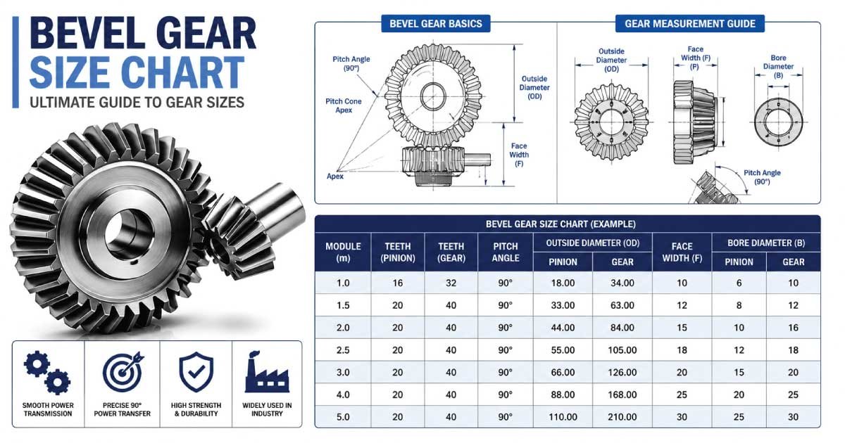
Bevel gears are among the most important mechanical power transmission components used in industrial machinery, automotive systems, agricultural equipment, and precision engineering applications. Their unique conical shape allows them to transfer motion and power between intersecting shafts, typically at a 90-degree angle, although other shaft angles are also possible.
Selecting the correct bevel gear size is critical for achieving smooth operation, maximum efficiency, longer service life, and reliable torque transmission. An incorrectly sized gear can lead to excessive wear, vibration, overheating, noise, and even premature equipment failure.
This comprehensive guide explains bevel gear sizing, dimensions, terminology, calculations, and practical selection methods. Whether you are an engineer, technician, student, maintenance professional, or DIY enthusiast, this guide will help you understand how bevel gear sizes are determined and how to choose the right gear for your application.
Bevel Gear Basics
A bevel gear is designed with teeth cut on the surface of a cone instead of a cylinder. This special geometry enables rotational power to be transmitted between intersecting shafts while maintaining efficient motion transfer. Understanding its construction is the first step toward selecting the correct size for any mechanical system.
Unlike spur gears that operate on parallel shafts, bevel gears transmit motion between shafts that intersect.
The most common shaft angle is:
- 90°
- 45°
- 60°
- 120°
- Custom angles
Bevel gears are commonly manufactured from:
- Carbon steel
- Alloy steel
- Stainless steel
- Cast iron
- Bronze
- Engineering plastics
Common applications include:
- Vehicle differentials
- Industrial gearboxes
- Mining machinery
- Marine equipment
- Agricultural machines
- Packaging equipment
- Robotics
- Aerospace systems
Types of Bevel Gears
Different bevel gear designs serve different mechanical purposes. Choosing the correct type depends on shaft arrangement, speed, load capacity, required smoothness, and manufacturing cost. Understanding these variations helps ensure proper gear sizing while improving efficiency, durability, and long-term operational performance.
Straight Bevel Gears
Straight bevel gears have straight teeth that extend toward the apex of the gear cone. They are simple to manufacture, economical, and suitable for moderate-speed applications where precision and smooth operation are less critical.
Typical uses include:
- Hand-operated machinery
- Low-speed gearboxes
- Agricultural equipment
- Industrial conveyors
Spiral Bevel Gears
Spiral bevel gears feature curved teeth that gradually engage during rotation, resulting in smoother power transmission, reduced vibration, quieter operation, and greater load capacity compared to straight bevel gears.
Advantages include:
- Higher efficiency
- Less noise
- Better load distribution
- Longer service life
- Higher operating speeds
Zerol Bevel Gears
Zerol bevel gears combine characteristics of straight and spiral bevel gears. Their curved teeth have virtually zero spiral angle, offering smoother engagement than straight bevel gears while remaining easier to manufacture than fully spiral designs.
Hypoid Gears
Although technically different from traditional bevel gears, hypoid gears are often grouped with them because of their similar appearance and function. They feature offset shaft centers and provide exceptionally smooth operation with excellent torque capacity.
Common applications include:
- Automotive rear axles
- Heavy-duty transmissions
- Industrial drive systems
Bevel Gear Terminology
Understanding bevel gear terminology makes it much easier to read manufacturer catalogs, compare specifications, perform calculations, and select compatible gears. These dimensions directly influence gear strength, speed ratio, efficiency, and overall mechanical performance in real-world applications.
Pitch Diameter
The pitch diameter is the theoretical diameter where mating gears roll together without slipping. It is one of the most important dimensions used when calculating gear ratios and selecting compatible bevel gears.
Formula:
Pitch Diameter = Module × Number of Teeth
Module
The module represents the size of individual gear teeth.
Formula:
Module = Pitch Diameter ÷ Number of Teeth
Typical metric modules include:
| Module (mm) | Common Applications |
|---|---|
| 1 | Small instruments |
| 1.5 | Light machinery |
| 2 | General equipment |
| 3 | Industrial drives |
| 4 | Heavy machinery |
| 5 | Mining equipment |
| 6 | Large industrial gearboxes |
| 8 | Heavy-duty drives |
| 10 | Steel mills |
Number of Teeth
The number of teeth directly determines the gear ratio when paired with another bevel gear. Larger tooth counts generally provide smoother operation, while fewer teeth can produce higher speed ratios within limited installation space.
Pressure Angle
The pressure angle defines the direction of force transmitted between mating gear teeth. Modern bevel gears most commonly use 20°, although 14.5° and 25° are also available for specialized applications.
Common pressure angles:
- 20°
- 25°
- 14.5°
Face Width
Face width measures the usable tooth length across the gear face. Wider face widths improve load distribution and increase torque capacity but also add weight, manufacturing cost, and installation space requirements.
Pitch Cone Angle
The pitch cone angle defines the angle formed by the pitch cone relative to the shaft axis. It varies depending on the gear ratio and ensures proper tooth engagement between mating bevel gears.
Bevel Gear Size Chart
Selecting the correct bevel gear begins with understanding standard dimensions used across most manufacturers. The following reference chart provides common module sizes, pitch diameters, outside diameters, and recommended applications to simplify gear selection during design, maintenance, or replacement projects.
| Module (mm) | Teeth | Pitch Diameter (mm) | Approx. Outside Diameter (mm) | Face Width (mm) | Common Application |
|---|---|---|---|---|---|
| 1 | 20 | 20 | 22 | 6 | Precision devices |
| 1.5 | 20 | 30 | 33 | 8 | Light equipment |
| 2 | 20 | 40 | 44 | 10 | Small machinery |
| 2.5 | 24 | 60 | 65 | 12 | Packaging machines |
| 3 | 24 | 72 | 78 | 15 | Industrial equipment |
| 4 | 25 | 100 | 108 | 20 | Heavy machinery |
| 5 | 30 | 150 | 160 | 25 | Mining equipment |
| 6 | 32 | 192 | 204 | 30 | Construction machinery |
| 8 | 36 | 288 | 304 | 40 | Steel plants |
| 10 | 40 | 400 | 420 | 50 | Large industrial drives |
Note: Dimensions shown above are general industry references. Actual values may vary slightly depending on the manufacturer, pressure angle, gear standard (ISO, AGMA, DIN), and specific design requirements.
How Bevel Gear Sizes Work
Bevel gear dimensions are interconnected, meaning a change in one measurement often affects several others. Understanding these relationships allows engineers and technicians to select gears that deliver the desired speed ratio, torque capacity, strength, and smooth operation without unnecessary oversizing or performance compromises.
For example:
- Increasing the module increases tooth size.
- Larger teeth improve load capacity.
- Increasing face width improves durability.
- More teeth usually produce smoother engagement.
- Larger pitch diameters increase overall gear size.
These parameters must be balanced carefully to achieve efficient and reliable performance.
Standard Bevel Gear Dimensions
Most bevel gears are manufactured according to internationally recognized standards to ensure compatibility, predictable performance, and easier replacement. Standard dimensions simplify equipment design while reducing manufacturing costs and allowing engineers to select gears confidently from multiple trusted suppliers.
Common standardized dimensions include:
| Dimension | Typical Range |
|---|---|
| Module | 1–10 mm |
| Teeth | 12–100 |
| Pressure Angle | 20° |
| Shaft Angle | 90° |
| Face Width | 6–50 mm |
| Gear Ratio | 1:1 to 6:1 |
| Materials | Steel, Cast Iron, Bronze |
Gear Ratio Explained
The gear ratio determines how rotational speed and torque are exchanged between two bevel gears. Selecting the proper ratio ensures machinery delivers the required performance while maintaining efficiency, reducing wear, and preventing unnecessary stress on gear teeth and supporting components.
Formula:
Gear Ratio = Driven Gear Teeth ÷ Driving Gear Teeth
Example:
Driving Gear = 20 Teeth
Driven Gear = 40 Teeth
Gear Ratio:
40 ÷ 20 = 2:1
This means:
- Output speed becomes half.
- Output torque approximately doubles.
- Power remains nearly constant (excluding efficiency losses).
👉 Looking for more accurate dimensions? Explore our Clevis Pin Size Chart collection for an Expert Guide and Professional Guide to selecting the correct mechanical component.
How to Measure Bevel Gears
Accurately measuring a bevel gear is essential when replacing worn components, designing new gear systems, or verifying manufacturer specifications. Even small measurement errors can affect gear meshing, increase noise, reduce efficiency, and shorten service life. Using proper measuring tools ensures the replacement gear performs exactly as intended.
Before measuring, clean the gear thoroughly to remove grease, rust, and debris.
Common measuring tools include:
- Vernier caliper
- Digital caliper
- Outside micrometer
- Gear tooth caliper
- Steel ruler
- Protractor
- Dial indicator
Measure Pitch Diameter
The pitch diameter is the theoretical circle where two mating gears engage. Since it cannot be measured directly, it is normally calculated using the module and number of teeth. This dimension is critical because it determines gear compatibility, speed ratio, and overall geometry.
Formula:
Pitch Diameter = Module × Number of Teeth
Example:
- Module = 4 mm
- Teeth = 25
Pitch Diameter:
4 × 25 = 100 mm
Count Gear Teeth
Counting gear teeth correctly ensures the proper gear ratio is maintained. Count every complete tooth around the gear once, starting from a marked tooth to avoid missing or double-counting. Accurate tooth counts are essential when ordering replacement gears or designing new drive systems.
Tips:
- Rotate the gear slowly.
- Mark the starting tooth.
- Count each full tooth only once.
Measure Face Width
Face width is the usable width of the gear tooth measured across the face of the gear. This dimension directly influences load distribution, contact area, and torque capacity. Wider face widths generally improve durability but require additional installation space.
Measure Bore Diameter
The bore is the center hole through which the gear mounts onto the shaft. Measure the inside diameter carefully using a caliper to ensure a proper fit. An incorrect bore size may result in slippage, vibration, or shaft damage during operation.
Check Shaft Angle
Most bevel gears are designed for shafts intersecting at 90 degrees, but other shaft angles are available for specialized machinery. Confirming the shaft angle ensures correct tooth contact and prevents uneven loading or premature wear after installation.
👉 Before choosing your next part, check our latest Split Pin Size Chart for a complete Expert Guide with professional sizing recommendations and practical tips.
Bevel Gear Design Calculations
Design calculations help engineers verify that a bevel gear can safely transmit the required power, torque, and rotational speed. Proper calculations reduce the risk of gear failure while improving efficiency, reliability, and service life in demanding industrial environments.
Important design parameters include:
- Module
- Pitch diameter
- Gear ratio
- Pitch cone angle
- Torque
- Rotational speed
- Power
- Face width
Pitch Diameter Formula
The pitch diameter forms the basis of many bevel gear calculations. Once the module and number of teeth are known, this value can be calculated quickly and used for determining gear geometry and compatibility with mating gears.
Pitch Diameter = Module × Teeth
Example:
Module = 5 mm
Teeth = 30
Pitch Diameter:
5 × 30 = 150 mm
Gear Ratio Formula
The gear ratio controls how speed and torque change between the driving and driven gears. Selecting the appropriate ratio is essential for achieving the desired machine performance while maintaining efficient power transmission.
Gear Ratio = Driven Teeth ÷ Driver Teeth
Example:
- Driver = 24 Teeth
- Driven = 48 Teeth
Ratio:
48 ÷ 24 = 2:1
Pitch Cone Angle Formula
The pitch cone angle defines the geometry of mating bevel gears and varies according to the gear ratio. Correct cone angles ensure smooth tooth engagement and even load distribution throughout the gear mesh.
For two intersecting shafts:
tan (Pitch Cone Angle) = Driver Teeth ÷ Driven Teeth
Engineering software or gear design standards are commonly used for precise calculations.
Pitch Line Velocity
Pitch line velocity represents the speed at which the gear teeth move through the pitch circle. It is an important factor when evaluating lubrication requirements, operating temperature, and expected gear wear.
Formula:
Velocity = (π × Pitch Diameter × RPM) ÷ 60
Higher pitch line velocities generally require improved lubrication and precision manufacturing.
Materials Used
Selecting the proper gear material is just as important as choosing the correct size. Material affects strength, wear resistance, corrosion protection, manufacturing cost, and overall operating life. The best choice depends on load conditions, operating environment, and maintenance requirements.
| Material | Advantages | Typical Applications |
|---|---|---|
| Alloy Steel | High strength, excellent wear resistance | Heavy industrial gearboxes |
| Carbon Steel | Affordable and durable | General machinery |
| Stainless Steel | Corrosion resistant | Food processing and marine equipment |
| Cast Iron | Good vibration damping | Medium-duty machines |
| Bronze | Excellent anti-friction properties | Worm and specialty gear systems |
| Engineering Plastic | Lightweight and quiet | Robotics and light automation |
👉 Need the right dimensions? Visit our detailed Snap Ring Size Chart to access an Expert Guide and Professional Guide for accurate size selection.
Choosing the Right Size
Choosing the correct bevel gear size involves balancing torque, speed, available installation space, operating conditions, and expected service life. Oversized gears increase cost and weight, while undersized gears may fail prematurely under heavy loads or continuous operation.
Consider the following factors:
- Required torque
- Input speed
- Output speed
- Available space
- Gear ratio
- Material
- Shaft diameter
- Operating temperature
- Lubrication method
- Shock loading
A systematic selection process helps avoid expensive redesigns and improves long-term equipment reliability.
Common Applications
Bevel gears are used wherever rotational motion must be transferred between intersecting shafts. Their ability to efficiently change the direction of power flow makes them essential in numerous industries ranging from automotive manufacturing to precision robotics and heavy industrial machinery.
Typical applications include:
- Automotive differentials
- Industrial gearboxes
- Mining equipment
- Agricultural machinery
- Marine propulsion systems
- Aerospace mechanisms
- Conveyor systems
- Printing presses
- Packaging machines
- Robotics
- Machine tools
- Construction equipment
Each application may require different gear sizes, materials, and tooth designs based on load, speed, and environmental conditions.
Common Sizing Mistakes
Incorrect gear selection often leads to poor performance, excessive noise, premature wear, and unexpected downtime. Understanding the most common sizing mistakes helps engineers and maintenance teams improve equipment reliability while reducing repair costs and extending component life.
Common mistakes include:
- Choosing the wrong module
- Ignoring pressure angle compatibility
- Selecting an incorrect gear ratio
- Using an undersized face width
- Overlooking shaft angle requirements
- Ignoring lubrication needs
- Choosing the wrong material
- Exceeding the recommended load capacity
- Miscalculating bore size
Always verify all dimensions before ordering or installing replacement gears.
Maintenance Tips
Routine maintenance significantly extends bevel gear life by reducing friction, preventing contamination, and identifying wear before serious damage occurs. A well-maintained gear system operates more efficiently, produces less noise, and minimizes costly unplanned downtime.
Best maintenance practices include:
- Inspect gears regularly for wear.
- Keep lubrication at recommended levels.
- Replace damaged bearings promptly.
- Check alignment after maintenance.
- Monitor operating temperature.
- Listen for unusual vibration or noise.
- Remove dirt and metal particles from the gearbox.
- Follow manufacturer service intervals.
Preventive maintenance is often less expensive than emergency repairs and helps maximize equipment availability.
Conclusion
Choosing the correct bevel gear size is fundamental to achieving reliable, efficient, and long-lasting power transmission. Understanding key dimensions such as module, pitch diameter, face width, pressure angle, bore size, and gear ratio enables engineers, mechanics, and equipment owners to make informed decisions when designing or replacing gear systems.
The bevel gear size chart provided in this guide offers a practical starting point, but final selection should always consider operating conditions, transmitted torque, shaft arrangement, material, and applicable standards such as ISO, AGMA, or DIN.
Combining accurate measurements, sound engineering calculations, and routine maintenance will help maximize gear performance, reduce downtime, and extend the service life of mechanical equipment across a wide range of industrial and commercial applications.
FAQs:
What is the standard bevel gear size?
There is no single standard bevel gear size because dimensions depend on the application, load requirements, gear ratio, and industry standards. However, common modules range from 1 mm to 10 mm, with pressure angles of 20 degrees and shaft angles of 90 degrees being widely used across industrial equipment.
How do I choose the correct bevel gear size?
Choose a bevel gear by evaluating the required torque, rotational speed, gear ratio, shaft angle, module, face width, material, and available installation space. Matching these factors with manufacturer specifications ensures reliable performance, proper tooth engagement, and a longer service life.
What is the most common pressure angle?
The most commonly used pressure angle for modern bevel gears is 20 degrees because it provides an effective balance between strength, smooth operation, and manufacturing simplicity. Other pressure angles, such as 14.5 degrees and 25 degrees, are used for specialized engineering applications.
Can bevel gears handle high torque?
Yes. Properly designed bevel gears manufactured from high-strength alloy steel with suitable heat treatment can transmit very high torque. Selecting the correct module, face width, material, and lubrication system is essential to achieving reliable performance under heavy-duty operating conditions.
What causes bevel gear failure?
Bevel gear failures commonly result from incorrect sizing, poor alignment, inadequate lubrication, excessive loads, contamination, overheating, manufacturing defects, or improper installation. Regular inspections, correct maintenance practices, and selecting gears according to engineering standards greatly reduce the risk of failure.

Engineer Hassan is a Mechanical Engineer with 16+ years of hands-on experience in mechanical hardware, fasteners, and workshop tools. He focuses on size selection, thread identification, and measurement, helping users choose the correct components with accuracy and safety.