
Choosing the correct gear rack size is one of the most important decisions in any mechanical power transmission system.
Whether you are designing industrial machinery, automotive steering systems, or automation equipment, understanding gear rack dimensions ensures better performance, longer service life, and precise motion control.
This complete guide covers the essential aspects of gear rack sizing, terminology, and selection factors.
What Is a Gear Rack and Why Does Its Size Matter?
A gear rack is a straight bar containing evenly spaced teeth that mesh with a pinion gear to convert rotary motion into linear movement. Selecting the correct rack size directly affects load capacity, motion accuracy, durability, operating efficiency, and compatibility with other mechanical components within the system.
Understanding the Standard Gear Rack Size Chart
A gear rack size chart provides standardized dimensions that manufacturers use when producing racks. These specifications help engineers and buyers choose compatible racks and pinions without requiring custom calculations. The chart typically includes module, pitch, tooth dimensions, pressure angle, and rack length information for easy comparison.
Common Information Included in a Gear Rack Size Chart
- Module (Metric)
- Diametral Pitch (Imperial)
- Pressure Angle
- Tooth Height
- Tooth Thickness
- Overall Rack Height
- Rack Width
- Standard Length
- Material Type
- Surface Hardness
Key Measurements Used in Gear Rack Sizing
Before selecting a gear rack, it’s important to understand the measurements that determine its compatibility. Every specification influences how smoothly the rack meshes with the pinion, how much force it can transmit, and how efficiently the system performs under varying operating conditions.
Important Gear Rack Dimensions
| Dimension | Description |
|---|---|
| Module | Determines tooth size in metric systems |
| Pitch | Distance between adjacent teeth |
| Tooth Height | Overall height of each tooth |
| Face Width | Width of the rack that contacts the pinion |
| Rack Length | Total linear length of the rack |
| Pressure Angle | Angle of tooth contact |
| Tooth Thickness | Width of each gear tooth |
Gear Rack Size Chart PDF
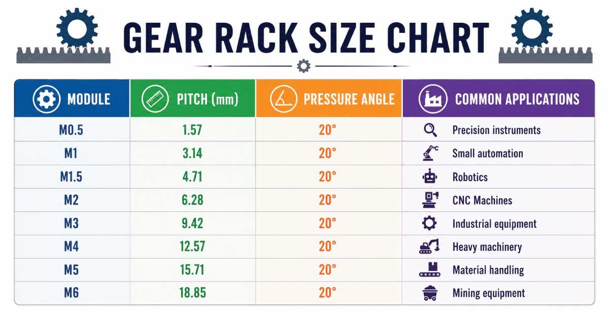
A Gear Rack Size Chart helps you choose the correct rack module for smooth and efficient power transmission. It lists standard module sizes, pitch, pressure angle, and common applications, making it easier to select the right gear rack for CNC machines, robotics, automation systems, industrial equipment, and heavy-duty machinery.
Metric Gear Rack Size Chart
Metric gear racks are widely used throughout Europe, Asia, and many international manufacturing industries. The module system simplifies gear sizing by maintaining standardized tooth proportions, making it easier to match racks and pinions produced by different manufacturers while ensuring proper engagement and reliable motion transfer.
| Module | Pitch (mm) | Pressure Angle | Common Applications |
|---|---|---|---|
| M0.5 | 1.57 | 20° | Precision instruments |
| M1 | 3.14 | 20° | Small automation |
| M1.5 | 4.71 | 20° | Robotics |
| M2 | 6.28 | 20° | CNC Machines |
| M3 | 9.42 | 20° | Industrial equipment |
| M4 | 12.57 | 20° | Heavy machinery |
| M5 | 15.71 | 20° | Material handling |
| M6 | 18.85 | 20° | Mining equipment |
Imperial Gear Rack Size Chart
Many industries in the United States continue using imperial gear rack standards measured by Diametral Pitch (DP). These systems provide compatibility with legacy machinery and industrial equipment, making DP-based racks a common choice for maintenance, repairs, and replacement applications across various manufacturing sectors.
| Diametral Pitch | Pressure Angle | Typical Industry |
|---|---|---|
| 16 DP | 20° | Precision equipment |
| 12 DP | 20° | Industrial automation |
| 10 DP | 20° | General machinery |
| 8 DP | 20° | Conveyor systems |
| 6 DP | 20° | Heavy-duty machines |
| 4 DP | 20° | Mining and construction |
How to Read a Gear Rack Size Chart Correctly
Reading a gear rack chart becomes simple once you understand what each specification represents. Begin by identifying the module or diametral pitch, then verify the pressure angle, tooth dimensions, rack length, and material. Ensuring these values match your pinion guarantees smooth operation and accurate linear movement.
Steps for Reading the Chart
- Identify the module or DP.
- Match the pressure angle.
- Check tooth dimensions.
- Verify rack length.
- Confirm face width.
- Review material specifications.
- Compare load capacity.
- Ensure compatibility with the pinion.
Common Gear Rack Materials
Material selection plays a significant role in determining gear rack strength, wear resistance, corrosion protection, and operating lifespan. Different materials suit different environments, ranging from lightweight automation systems to heavy industrial applications exposed to high loads, moisture, chemicals, or abrasive operating conditions.
Popular Materials
- Carbon Steel
- Alloy Steel
- Stainless Steel
- Hardened Steel
- Aluminum
- Brass
- Engineering Plastic
Each material offers different benefits depending on strength requirements, operating temperature, corrosion resistance, and maintenance expectations.
Factors That Influence Gear Rack Size Selection
Choosing the correct gear rack involves much more than matching dimensions. Engineers evaluate operating conditions, system performance, expected loads, and environmental factors before selecting the most suitable rack size. Proper planning minimizes maintenance costs while maximizing operational reliability and overall equipment efficiency.
Consider These Factors
- Maximum operating load
- Linear travel distance
- Speed requirements
- Accuracy level
- Environmental conditions
- Available installation space
- Lubrication method
- Expected service life
Benefits of Using the Correct Gear Rack Size
Using the right gear rack size improves machine efficiency while reducing unnecessary wear on both the rack and pinion. Proper sizing also minimizes vibration, decreases maintenance frequency, and enhances positioning accuracy, making the entire mechanical system more reliable and cost-effective throughout its operational lifespan.
Major Advantages
- Improved efficiency
- Longer component life
- Lower maintenance costs
- Better positioning accuracy
- Reduced mechanical noise
- Smooth motion transmission
- Higher load capacity
- Enhanced operational safety
Common Mistakes to Avoid When Choosing Gear Rack Sizes
Many equipment failures result from selecting incorrect gear rack dimensions or incompatible pinions. Avoiding these common mistakes helps maintain smooth operation, reduces downtime, and prevents premature wear, ensuring the rack performs efficiently under its intended operating conditions.
Avoid These Errors
- Choosing the wrong module
- Ignoring pressure angle compatibility
- Selecting insufficient rack length
- Overlooking load requirements
- Using improper materials
- Skipping lubrication considerations
- Ignoring installation tolerances
Gear Rack Calculations Every Buyer Should Understand
Understanding basic gear rack calculations helps ensure the selected rack performs efficiently under real operating conditions. These calculations determine travel distance, load capacity, and proper pinion engagement. Even a basic knowledge of gear formulas allows engineers, technicians, and buyers to make informed decisions and avoid costly sizing mistakes.
Essential Gear Rack Calculations
| Calculation | Formula |
|---|---|
| Linear Travel | Pinion Circumference × Number of Revolutions |
| Circular Pitch | π × Module |
| Pitch Diameter | Module × Number of Teeth |
| Tooth Load | Force ÷ Number of Engaged Teeth |
| Rack Speed | Pinion RPM × Circumference |
How to Match a Gear Rack with the Right Pinion
Selecting the correct pinion is just as important as choosing the proper rack. Both components must share identical tooth geometry for smooth engagement. Any mismatch can increase wear, create excessive noise, reduce positioning accuracy, and significantly shorten the lifespan of the complete gear drive system.
Pinion Matching Checklist
- Same module or diametral pitch
- Matching pressure angle
- Compatible tooth profile
- Appropriate material hardness
- Correct face width
- Suitable number of teeth
- Proper mounting alignment
- Similar manufacturing standards
Standard Gear Rack Lengths Available
Most manufacturers produce gear racks in standardized lengths to simplify installation and reduce manufacturing costs. Longer travel distances are typically achieved by joining multiple rack sections together with precision-machined ends, ensuring smooth tooth alignment and uninterrupted motion across the entire system.
Typical Standard Lengths
| Rack Length | Common Use |
|---|---|
| 500 mm | Compact machinery |
| 1000 mm | CNC equipment |
| 1500 mm | Automation systems |
| 2000 mm | Material handling |
| 3000 mm | Industrial production lines |
Also Read:
Gear Rack Pressure Angles Explained
The pressure angle determines how force transfers between the rack and pinion during operation. Modern systems commonly use a 20-degree pressure angle because it provides an excellent balance between strength, efficiency, and durability. Older equipment may still use 14.5-degree designs for compatibility reasons.
Common Pressure Angles
- 20° (Most common)
- 14.5° (Older equipment)
- 25° (Heavy-duty applications)
Applications of Different Gear Rack Sizes
Different industries require different gear rack sizes depending on speed, accuracy, and load capacity. Smaller modules provide precise positioning for delicate equipment, while larger modules handle greater forces in heavy industrial environments where strength and durability are the primary priorities.
Industry Applications
| Gear Rack Size | Typical Application |
|---|---|
| M0.5–M1 | Medical devices |
| M1–M2 | Robotics |
| M2–M3 | CNC machines |
| M3–M4 | Packaging equipment |
| M4–M6 | Industrial automation |
| M6+ | Mining and heavy machinery |
Choosing the Right Material for Your Application
Material selection depends on environmental conditions, operating loads, maintenance schedules, and expected service life. While hardened steel provides maximum durability for demanding applications, stainless steel offers corrosion resistance, and engineering plastics are suitable for lightweight, low-noise systems with minimal loads.
Material Comparison
| Material | Main Benefit |
|---|---|
| Carbon Steel | Economical |
| Hardened Steel | Excellent wear resistance |
| Stainless Steel | Corrosion resistance |
| Alloy Steel | High strength |
| Aluminum | Lightweight |
| Plastic | Quiet operation |
Also Read:
Installation Tips for Better Performance
Proper installation is essential for achieving maximum gear rack performance. Even a high-quality rack can fail prematurely if alignment, mounting, or lubrication are neglected. Careful installation improves efficiency, minimizes vibration, and extends the operating life of both the rack and the pinion.
Best Installation Practices
- Align the rack accurately.
- Secure mounting bolts evenly.
- Check pinion backlash.
- Apply suitable lubrication.
- Verify tooth engagement.
- Inspect alignment after installation.
- Test operation before full production.
- Re-tighten fasteners after initial use.
Maintenance Tips to Extend Gear Rack Life
Routine maintenance helps prevent premature wear and unexpected equipment failures. Regular inspections, cleaning, lubrication, and alignment checks ensure smooth operation while reducing repair costs. Preventive maintenance significantly extends the service life of both the gear rack and its mating pinion.
Maintenance Checklist
- Clean dirt and debris regularly.
- Lubricate gear teeth.
- Inspect for tooth wear.
- Check bolt tightness.
- Monitor alignment.
- Replace damaged sections promptly.
- Inspect lubrication quality.
- Schedule periodic inspections.
Also Read:
Signs Your Gear Rack Needs Replacement
Over time, gear racks naturally wear due to continuous operation and heavy loads. Recognizing early warning signs helps prevent downtime and costly equipment damage. Timely replacement ensures consistent performance, accurate motion control, and safe operation across the entire mechanical system.
Common Warning Signs
- Excessive tooth wear
- Cracked or broken teeth
- Increased operating noise
- Poor positioning accuracy
- Uneven motion
- Visible corrosion
- Excessive backlash
- Frequent maintenance issues
Custom vs. Standard Gear Racks
While standard gear racks satisfy most industrial requirements, some specialized applications demand custom designs. Custom racks provide tailored dimensions, materials, coatings, and tooth profiles to meet unique performance requirements, though they generally involve higher costs and longer manufacturing lead times.
Comparison
| Standard Gear Racks | Custom Gear Racks |
|---|---|
| Lower cost | Higher cost |
| Faster availability | Longer production time |
| Standard dimensions | Custom dimensions |
| Easy replacement | Specialized applications |
| Widely available | Made to order |
Expert Tips for Buying the Right Gear Rack
Purchasing a gear rack involves more than selecting a size from a catalog. Evaluating manufacturer quality, material specifications, machining precision, and application requirements helps ensure you receive a reliable product that delivers long-term value and dependable performance.
Buying Checklist
- Confirm module or DP.
- Verify pressure angle.
- Match the pinion specifications.
- Review material quality.
- Check hardness ratings.
- Compare manufacturing tolerances.
- Confirm rack length.
- Purchase from reputable suppliers.
- Request technical documentation.
- Review warranty coverage.
Final Thoughts
Selecting the correct gear rack size is essential for achieving smooth motion, reliable performance, and extended equipment life. Understanding key factors such as size charts, dimensions, calculations, materials, installation methods, and maintenance requirements helps ensure the right component is chosen for each application.
Proper gear rack selection and accurate matching with the pinion gear improve motion accuracy, reduce wear, and enhance overall system efficiency. Careful planning also helps prevent alignment issues, minimize downtime, and maintain consistent performance in mechanical power transmission systems.
By considering application requirements and following recommended installation and maintenance practices, you can maximize the lifespan and value of your gear rack system. A well-selected gear rack provides dependable operation, improved productivity, and long-term reliability across a wide range of industrial applications.
Frequently Asked Questions (FAQs)
What is the most common gear rack pressure angle?
The 20-degree pressure angle is the industry standard because it provides an excellent balance between tooth strength, smooth engagement, load capacity, and durability. It is widely used in industrial machinery, automation systems, and motion-control applications because it offers reliable performance and efficient power transmission.
How do I know which gear rack size I need?
To select the correct gear rack size, consider factors such as required load capacity, travel distance, module or diametral pitch, pressure angle, and compatibility with the pinion gear. Reviewing your machine specifications and operating conditions ensures you choose a rack that provides accurate movement, proper engagement, and long service life.
Can different modules work together?
No. A gear rack and pinion must have matching module or diametral pitch and pressure angle to operate correctly. Using mismatched components can cause poor tooth engagement, excessive noise, increased friction, accelerated wear, and potential failure of the gear system due to improper load distribution.
Which material lasts the longest?
Hardened alloy steel generally provides the longest service life because it offers excellent wear resistance, high strength, and superior durability under demanding operating conditions. It is commonly used in heavy-duty industrial applications where gear racks must withstand repeated loads, high speeds, and continuous mechanical stress.
How often should gear racks be lubricated?
Lubrication frequency depends on factors such as operating speed, load, environment, and usage frequency. Heavy-duty gear rack systems typically require more frequent lubrication than lightly loaded or occasional-use applications. Regular lubrication reduces friction, minimizes wear, improves movement efficiency, and helps extend the overall service life of the components.

Engineer Hassan is a Mechanical Engineer with 16+ years of hands-on experience in mechanical hardware, fasteners, and workshop tools. He focuses on size selection, thread identification, and measurement, helping users choose the correct components with accuracy and safety.