
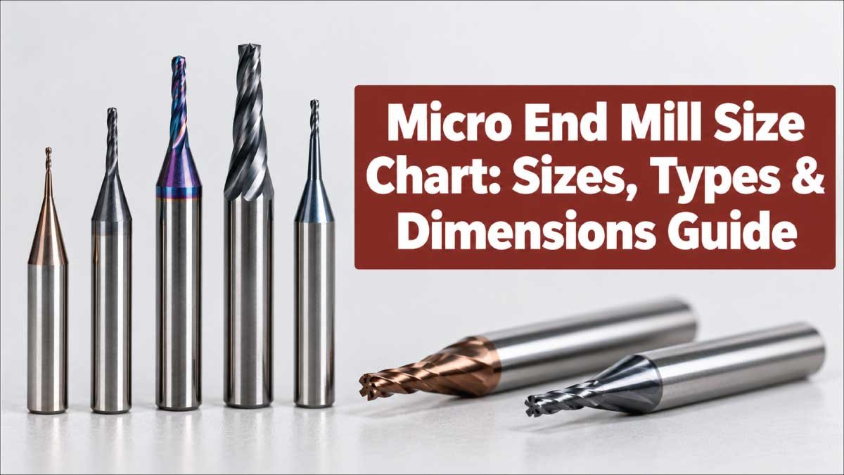
Micro end mills are precision cutting tools designed for machining very small features, narrow slots, fine pockets, miniature cavities, and detailed contours. Choosing the correct tool is more complicated than simply selecting the smallest available diameter. Micro end mill size affects rigidity, cutting depth, surface finish, tool life, and the level of detail a machine can produce.
This micro end mill size chart guide explains common cutter diameters, shank sizes, flute configurations, cutting lengths, materials, geometries, and applications. It also covers how to select and measure a micro end mill while avoiding common sizing mistakes.
What Is a Micro End Mill?
A micro end mill is a miniature version of a conventional end milling cutter. It has a small cutting diameter and is manufactured for precision machining where ordinary milling cutters are too large to produce the required feature.
Micro end mills are commonly used on CNC milling machines, machining centers, micro-machining equipment, and high-speed spindles. Depending on the design, they can cut materials such as aluminum, copper alloys, plastics, tool steels, stainless steels, and other engineering materials.
The term micro end mill does not always represent one universal diameter range. Different manufacturers and industries may define micro tooling differently. In practice, cutters with diameters around 0.1 mm to 3 mm are commonly encountered in micro-machining applications, although tools outside this range may also be marketed for miniature machining.
Important dimensions include:
Cutting diameter: The diameter of the cutting portion.
Shank diameter: The diameter held by the tool holder or collet.
Cutting length: The axial length containing cutting edges.
Overall length: The complete length of the tool.
Number of flutes: The number of cutting edges.
Helix angle: The angle of the cutting edge around the tool.
Corner geometry: Square, ball nose, corner radius, or other profiles.
Micro End Mill Size Chart
The following chart provides practical diameter categories rather than claiming a universal manufacturer standard. Exact dimensions, cutting lengths, and shank configurations vary by tool design.
| Micro End Mill Diameter | Approx. Inch Equivalent | Typical Use | Rigidity Consideration |
|---|---|---|---|
| 0.10 mm | 0.0039 in | Extremely fine features | Very high sensitivity |
| 0.20 mm | 0.0079 in | Fine grooves and details | Very delicate |
| 0.30 mm | 0.0118 in | Small pockets and slots | Delicate |
| 0.50 mm | 0.0197 in | Fine precision machining | High sensitivity |
| 0.75 mm | 0.0295 in | Small cavities and profiles | Sensitive |
| 1.00 mm | 0.0394 in | General micro-machining | Moderate |
| 1.50 mm | 0.0591 in | Small pockets and contours | Better rigidity |
| 2.00 mm | 0.0787 in | General miniature machining | Good |
| 2.50 mm | 0.0984 in | Small features and slots | Good |
| 3.00 mm | 0.1181 in | Larger miniature features | Higher rigidity |
These values describe cutter diameter, not necessarily shank diameter. A tool with a 1 mm cutting diameter may use a larger shank depending on its construction.
Common Micro End Mill Dimensions
Micro end mills have several dimensions that should be considered together. Diameter is important, but it does not completely describe the tool.
Cutting Diameter
The cutting diameter determines the smallest practical width of a machined feature. A smaller diameter allows the cutter to enter narrower areas and create finer details.
However, using a smaller tool solely because it fits a feature is not always desirable. A larger cutter is generally more rigid when it can perform the required operation.
For example, if a pocket allows a 2 mm cutter, there may be little reason to use a 0.5 mm cutter unless the geometry specifically requires it.
Shank Diameter
The shank is the non-cutting portion secured inside the holder.
Common micro-tool shank configurations include miniature cylindrical shanks, with exact sizes depending on the manufacturer and tool series. Some product families use a consistent shank diameter across several cutting diameters, while others use different shanks for different cutter sizes.
Always match the shank to the:
- Collet
- Tool holder
- Shrink-fit system
- Hydraulic holder
- Machine spindle
- Manufacturer’s recommended gripping system
Cutting Length
Cutting length refers to the portion of the cutter that can actively engage the workpiece.
A longer cutting length provides greater reach but can reduce rigidity. This becomes particularly important with very small diameters because micro cutters are already vulnerable to deflection and breakage.
Overall Length
Overall length is the complete distance from the tool tip to the end of the shank.
Long-reach micro end mills may be useful for deep cavities, but excessive stick-out can increase vibration. Whenever possible, use the shortest tool extension that provides the required clearance.
Micro End Mill Size by Diameter
Diameter selection should begin with the smallest feature that must actually be machined.
0.1 to 0.3 mm Micro End Mills
Ultra-small cutters in this range are intended for extremely fine features.
They may be used for miniature slots, tiny grooves, small mold details, electronics-related components, and precision micro-machining.
Their very small cross-section makes them especially sensitive to:
- Runout
- Vibration
- Excessive feed
- Excessive depth of cut
- Poor workholding
- Incorrect tool engagement
These tools demand a highly controlled machining setup.
0.5 to 1 mm Micro End Mills
This range is commonly useful for fine CNC work where a conventional small cutter is still too large.
They can be appropriate for small pockets, narrow slots, miniature contours, engraving-related machining, and mold details.
The exact cutting parameters should always come from the tool geometry, material, machine capability, and manufacturer’s recommendations.
1 to 2 mm Micro End Mills
Tools in this range provide a useful balance between miniature feature capability and cutter rigidity.
They are often suitable for:
- Small pockets
- Narrow channels
- Fine profiles
- Small holes when milling is appropriate
- Mold and die details
- Precision components
Compared with ultra-small cutters, they are generally easier to handle and less fragile.
2 to 3 mm Micro End Mills
At the upper end of many micro-tooling ranges, these cutters can provide substantially better rigidity while still allowing relatively small features.
They are useful when the workpiece geometry does not require extremely tiny cutting diameters.
Types of Micro End Mills
Micro end mills are available in several geometries. The correct type depends on the shape that needs to be produced and the material being machined.
Square End Micro Mills
Square end mills have a flat cutting end and are useful for producing:
- Flat-bottom pockets
- Slots
- Shoulders
- Vertical walls
- General contouring
They are often the first choice for conventional 2D and 2.5D miniature milling operations.
Ball Nose Micro End Mills
Ball nose cutters have a rounded cutting tip.
They are particularly useful for:
- 3D contours
- Curved surfaces
- Mold cavities
- Sculptured surfaces
- Fine finishing
A ball nose tool’s effective cutting diameter changes with tool engagement and surface geometry, so machining strategy matters considerably.
Corner Radius Micro End Mills
Corner-radius cutters combine a flat cutting region with a small radius at the edge.
The radius can reduce sharp corner stress and may improve tool durability in suitable applications.
Tapered Micro End Mills
Tapered cutters have a cutting section that changes diameter along its length.
They can be useful for specialized cavity machining, mold work, and applications requiring angled walls or additional tool clearance.
Micro End Mill Flute Count Chart
Flute count influences chip evacuation, available flute space, feed capability, and the type of material or operation for which a tool is designed.
| Flute Count | General Characteristics | Common Applications |
|---|---|---|
| 1 Flute | Large chip space | Plastics and selected nonferrous applications |
| 2 Flute | Good chip clearance | Aluminum, plastics, slotting |
| 3 Flute | Balance of chip space and cutting edges | Various nonferrous applications |
| 4 Flute | More cutting edges | Finishing and harder materials |
| 5+ Flute | High tooth count | Specialized finishing and high-feed applications |
There is no universally correct flute count for every material. Tool geometry, coating, helix, machine speed, coolant, workpiece material, and cutting strategy all influence the appropriate selection.
Micro End Mill Materials and Coatings
The tool substrate affects hardness, wear resistance, toughness, and cutting performance.
Solid Carbide Micro End Mills
Solid carbide is widely used for miniature cutting tools because it provides the stiffness and wear resistance required for precision machining.
Micro end mills are especially sensitive to deflection, so carbide construction is commonly favored for demanding CNC applications.
HSS Micro End Mills
High-speed steel can be used for certain small milling tools, particularly where toughness, cost, or machining conditions make it appropriate.
However, the choice between HSS and carbide should be based on the specific tool design and application rather than diameter alone.
Coated Micro End Mills
Micro end mills may be supplied with specialized coatings intended to improve wear resistance, reduce friction, or support machining particular materials.
Coating selection should match the workpiece and cutting conditions. A coating suitable for one material may not provide the same advantages in another.
Also Read:
How to Choose the Correct Micro End Mill Size
Selecting a micro end mill should be treated as a geometry-and-machining problem rather than simply a diameter choice.
1. Check the Smallest Feature
Start by identifying the narrowest slot, internal radius, pocket, or contour that must be machined.
Choose a diameter that can physically access the feature while leaving enough clearance for the cutting path.
2. Avoid Oversizing and Undersizing
An oversized cutter cannot enter the required geometry.
An unnecessarily undersized cutter may introduce additional problems such as reduced rigidity, slower machining, greater sensitivity to runout, and increased breakage risk.
Use the largest practical cutter that satisfies the geometry.
3. Check Required Cutting Depth
Compare the required machining depth with the tool’s available cutting length.
Do not assume that a tool with a particular diameter automatically has enough flute length for a deep feature.
4. Consider Tool Stick-Out
Keep the unsupported tool length as short as practical.
Long stick-out increases the tool’s tendency to deflect and vibrate, which can affect dimensional accuracy and surface finish.
5. Match the Material
Different workpiece materials require different tool geometries and cutting approaches.
Consider whether the workpiece is:
- Aluminum
- Brass
- Copper
- Plastic
- Stainless steel
- Tool steel
- Hardened material
- Composite material
Tool manufacturers often provide separate recommendations for these material groups.
Also Read:
Micro End Mill Size and Feature Size
A micro end mill should not automatically be selected at exactly the same size as the feature.
For example, a narrow slot may require a cutter smaller than the final slot width so that the tool can interpolate the geometry accurately.
For internal corners, the cutter diameter also influences the minimum achievable corner radius.
Internal Corner Considerations
A square end mill cannot normally create a perfectly sharp internal corner because its circular cutting path leaves a radius.
This means the cutter diameter and corner radius should be considered during CAD design.
For very small internal features, a smaller cutter may be necessary to reduce the remaining corner radius.
How to Measure a Micro End Mill
Accurate measurement is important when identifying an unknown cutter or checking whether a tool matches a machining requirement.
Measure the Cutting Diameter
Use a suitable precision measuring instrument to determine the diameter of the cutting portion.
Because micro end mills are extremely small, ordinary measuring tools may not provide sufficient resolution or may damage delicate cutting edges.
Measure the Shank
Measure the cylindrical shank separately from the cutting diameter.
Do not assume that the shank and cutting diameter are identical.
Measure Cutting Length
Identify the axial length of the cutting portion rather than measuring the entire tool.
Measure Overall Length
Measure from the end of the cutting tip to the opposite end of the shank.
When documenting a tool, record all measurements separately rather than describing it only by diameter.
Also Read:
Micro End Mill Size Selection by Application
Different machining operations can require different geometries and dimensions.
| Application | Typical Tool Style | Important Selection Factor |
|---|---|---|
| Fine slotting | Square end | Diameter and chip clearance |
| Small pockets | Square end | Diameter and cutting length |
| 3D contours | Ball nose | Tip radius and reach |
| Mold details | Ball nose or corner radius | Surface geometry |
| Sharp-feature machining | Square end | Small diameter |
| Deep miniature cavities | Long-reach design | Rigidity and stick-out |
| Plastic machining | 1–2 flute options | Chip evacuation |
| Fine finishing | Higher flute designs | Surface requirements |
These are general application relationships, not universal tooling rules. The actual tool should be selected according to the workpiece, machine, geometry, and manufacturer’s specifications.
Micro End Mill vs Standard End Mill
The primary difference is scale and the type of machining each tool is intended to perform.
| Feature | Micro End Mill | Standard End Mill |
|---|---|---|
| Diameter | Very small | Generally larger |
| Feature capability | Fine miniature details | General machining |
| Rigidity | More sensitive | Generally higher |
| Runout sensitivity | Very high | Lower relative sensitivity |
| Breakage risk | Higher for very small tools | Generally lower |
| Typical work | Small precision features | General pockets and profiles |
| Machine requirements | Often benefits from precision/high-speed setups | Broad range of machines |
A micro end mill is not simply a smaller standard cutter. Its small diameter makes setup quality, spindle condition, tool holding, runout, and machining parameters much more critical.
Common Micro End Mill Problems
Even a correctly sized cutter can fail if the machining setup is unsuitable.
Tool Breakage
Breakage can result from excessive cutting load, excessive stick-out, vibration, runout, incorrect cutting parameters, or inadequate chip evacuation.
Because a 0.2 mm cutter has very little cross-sectional area compared with a larger cutter, relatively small changes in cutting conditions can have significant effects.
Poor Surface Finish
Poor finish may be caused by:
- Tool deflection
- Excessive vibration
- Worn cutting edges
- Incorrect feed
- Excessive radial engagement
- Inadequate workholding
- Spindle runout
The cutter diameter alone does not determine surface quality.
Chatter
Chatter occurs when the cutting system becomes dynamically unstable.
With micro tools, chatter can be particularly damaging because the cutter has limited structural strength. Reducing unnecessary tool extension and improving workholding can help create a more stable machining system.
Premature Wear
Tool wear can accelerate when the cutter is used with unsuitable cutting conditions or when the workpiece material is too demanding for the selected tool.
A worn micro end mill may gradually produce dimensional errors before complete breakage occurs.
Tips for Using Micro End Mills
Small cutters require careful handling from tool installation through machining.
- Minimize runout at the tool holder and spindle.
- Keep tool stick-out as short as practical.
- Use an appropriate collet or precision holder.
- Keep the workpiece firmly secured.
- Select the cutter based on the actual feature geometry.
- Avoid using an unnecessarily small tool.
- Follow the tool manufacturer’s recommended cutting parameters.
- Provide suitable chip evacuation.
- Inspect the tool for wear and damage.
- Avoid handling cutting edges directly.
- Verify machine and spindle capability before using miniature tools.
- Use suitable coolant or lubrication when recommended for the workpiece and tool.
Micro End Mill Size Chart: Quick Selection Guide
For a quick starting point, the following chart connects common diameter ranges with the type of work they may support.
| Diameter Range | General Feature Capability | Primary Consideration |
|---|---|---|
| 0.10–0.30 mm | Extremely fine details | Maximum precision and stability |
| 0.30–0.50 mm | Very small slots and features | Runout and breakage |
| 0.50–1.00 mm | Fine pockets and profiles | Balance of detail and rigidity |
| 1.00–2.00 mm | Small general-purpose features | Geometry and material |
| 2.00–3.00 mm | Larger miniature features | Reach and cutting conditions |
This chart is intended as a selection framework, not a substitute for a manufacturer’s dimensional drawing or cutting-data table.
Important Specifications to Check Before Buying
When comparing micro end mills, diameter should be only one part of the specification.
Check:
- Cutting diameter
- Shank diameter
- Number of flutes
- Cutting length
- Overall length
- Helix angle
- End geometry
- Corner radius
- Tool substrate
- Coating
- Workpiece compatibility
- Recommended spindle speed
- Recommended feed
- Recommended depth of cut
- Coolant or lubrication requirements
These specifications determine whether a particular micro end mill is appropriate for the intended operation.
Frequently Asked Questions About Micro End Mill Sizes
What is the smallest micro end mill size?
Micro end mills are available in extremely small diameters, including tools around 0.1 mm, although availability depends on the manufacturer and tool series. Smaller specialized tools may also exist.
What size is a micro end mill?
There is no single universal definition. Micro end mills are commonly associated with miniature diameters, often ranging from approximately 0.1 mm to 3 mm, with specialized products extending beyond that range.
What is the best micro end mill diameter?
There is no universally best diameter. Select the largest practical diameter that can access the required geometry. Larger miniature cutters generally provide better rigidity than extremely small ones.
Are micro end mills made from carbide?
Yes. Solid carbide is widely used for micro end mills because miniature tools benefit from high stiffness and wear resistance. Other tool materials can also be used for specific applications.
What is the difference between a micro end mill and a small end mill?
The terminology varies among manufacturers. A micro end mill generally refers to a tool designed for very small-scale precision machining, while “small end mill” is a broader description that does not necessarily indicate a particular diameter range.
Can a micro end mill cut steel?
Yes, suitable micro end mills can be designed for steel and other difficult materials. The tool substrate, coating, geometry, machine rigidity, and cutting conditions must all be appropriate for the material.
Why do micro end mills break so easily?
Their small diameter gives them a very small cross-sectional area. Excessive cutting force, runout, vibration, tool extension, or unsuitable cutting parameters can therefore cause failure much more quickly than with larger cutters.
How do I choose between a 1 mm and 2 mm micro end mill?
First check whether both diameters can produce the required geometry. If both can access the feature, the 2 mm cutter may offer greater rigidity, while the 1 mm tool may be necessary for narrower areas or smaller radii.
Final Takeaway
A Micro End Mill Size Chart is useful for comparing cutter diameters, but diameter alone should never determine tool selection. Cutting length, shank diameter, flute count, tool geometry, material, coating, reach, and machining conditions all influence performance.
For the best results, begin with the smallest feature in the part, choose the largest cutter that can safely produce that geometry, minimize tool stick-out, control runout, and follow the cutting recommendations provided for the specific tool. Exact dimensions and cutting data can vary significantly between manufacturers, so the product drawing and technical documentation should be checked before machining.

Engineer Hassan is a Mechanical Engineer with 16+ years of hands-on experience in mechanical hardware, fasteners, and workshop tools. He focuses on size selection, thread identification, and measurement, helping users choose the correct components with accuracy and safety.