
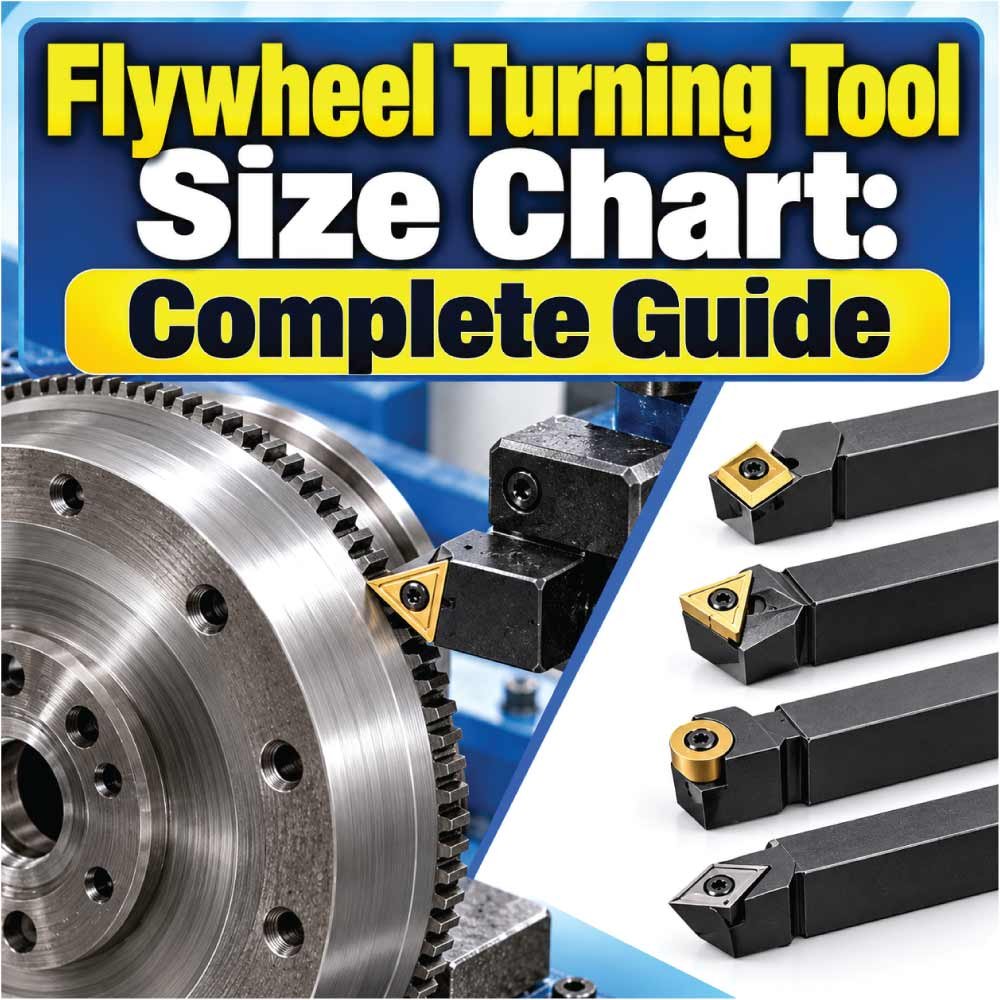
A flywheel turning tool makes it easier to rotate an engine flywheel manually during procedures such as valve adjustment, timing work, clutch inspection, compression checks, and engine assembly. The difficult part is choosing a tool that actually matches the flywheel teeth, ring gear profile, access area, and engine design.
Unlike a socket, wrench, or drill bit, flywheel turning tools do not follow one universal size system. Some engage directly with ring-gear teeth, while others fit a specific crankshaft or flywheel bolt. Tool dimensions can also vary significantly between manufacturers.
This flywheel turning tool size chart explains the measurements that matter, the main tool types, how to measure a flywheel, how to select the correct tool, and which specifications should be verified before purchase or use.
What Is a Flywheel Turning Tool?
A flywheel turning tool is a hand-operated tool designed to rotate an engine’s flywheel or flexplate through the ring gear. It provides controlled rotation without requiring the technician to turn the engine using a crankshaft pulley bolt.
The tool is particularly useful when an engine must be positioned at a precise point. For example, a technician may need to rotate the crankshaft slowly until timing marks align or until a particular cylinder reaches top dead center.
A typical flywheel turning tool may include:
- A handle or turning bar for manual rotation.
- A hook, pin, or tooth-engaging mechanism.
- An adjustable or fixed engagement section.
- A shaft designed to reach the flywheel through an inspection opening.
- A profile intended to work with a particular ring gear.
The important point is that tool size is determined by the engagement method, not simply by the overall length of the tool.
Flywheel Turning Tool Size Chart
There is no universal numerical size chart covering every flywheel turning tool. Manufacturers design tools around different ring gears, tooth profiles, access openings, and engine applications.
The following chart is therefore a selection framework rather than a fabricated universal specification chart.
| Measurement / Feature | What to Check | Why It Matters |
|---|---|---|
| Ring gear tooth size | Tooth dimensions and profile | Determines engagement |
| Tooth pitch | Distance between corresponding tooth points | Helps match the engagement mechanism |
| Flywheel diameter | Outside diameter of ring gear/flywheel | Helps identify application |
| Tool reach | Distance from handle to engagement point | Must reach the ring gear |
| Engagement width | Contact width of hook or pin | Must fit securely |
| Access opening | Width and depth of inspection area | Determines physical clearance |
| Handle length | Overall operating length | Affects leverage and access |
| Engagement style | Hook, pin, gear, or bolt-drive | Must match the flywheel system |
| Application | Engine-specific or universal | Helps prevent incompatibility |
Always treat the engine manufacturer’s specifications and the tool manufacturer’s application information as the final authority when an exact tool dimension is required.
How Flywheel Turning Tool Sizes Are Determined
The most important measurement is the interface between the tool and the flywheel. A tool can have a suitable overall length and still be unusable if its engagement point does not match the ring gear.
Ring Gear Tooth Profile
Many flywheel turning tools engage the teeth around the outside of a flywheel or flexplate. The engagement mechanism must fit the tooth geometry securely.
Two ring gears can have similar diameters but different tooth dimensions. Consequently, flywheel diameter alone should not be used to select a turning tool.
Tool Reach
Reach describes how far the engagement mechanism extends from the handle or body.
A tool with insufficient reach may not enter deeply enough through the inspection opening. Excessive reach is not automatically better either, because it can create clearance problems inside a confined engine housing.
Engagement Width
The hook, pin, or tooth-engaging portion needs enough contact with the ring gear to rotate the flywheel without slipping.
The exact engagement dimensions depend on the tool design. Some tools are adjustable, while others are manufactured for a specific range or application.
Access Clearance
The inspection opening can be just as important as the flywheel itself.
Before selecting a tool, consider:
- Opening width.
- Opening depth.
- Available angle.
- Nearby housing components.
- Starter position.
- Ring gear location.
- Space required for the handle.
Types of Flywheel Turning Tools
Different engines and repair procedures use different turning mechanisms. Understanding the tool type helps narrow down the correct size and design.
Ring Gear Flywheel Turning Tool
This type directly engages the flywheel or flexplate ring gear.
It is commonly useful when the engine must be rotated gradually and the ring gear is accessible through a designated opening.
Its main sizing considerations are:
- Ring gear tooth geometry.
- Engagement depth.
- Tool reach.
- Access opening.
- Hook or pin dimensions.
Flywheel Turning Bar
A turning bar provides a simple manual method of rotating the flywheel. Depending on the design, it may use a dedicated engagement end or another mechanical interface.
The bar needs sufficient length and strength for the intended application without creating excessive leverage against components that were not designed for it.
Flywheel Turning Tool With Adjustable Engagement
Some tools allow the engagement position or width to be adjusted.
Adjustability can make a tool useful across multiple applications, but it does not guarantee compatibility with every flywheel. The actual adjustment range must still cover the required dimensions.
Crankshaft Turning Tool
A crankshaft turning tool operates through the crankshaft rather than directly engaging the flywheel ring gear.
This distinction is important because a crankshaft turning tool size chart is not interchangeable with a flywheel turning tool size chart.
Flywheel Turning Tool Dimensions to Check
When comparing tools, avoid focusing on only one measurement. Several dimensions can affect whether a tool works correctly.
| Dimension | Typical Question to Ask | Selection Importance |
|---|---|---|
| Overall length | Can the tool be operated comfortably? | Medium |
| Working reach | Can it reach the ring gear? | High |
| Engagement width | Does it fit the tooth area? | High |
| Engagement depth | Does it sit securely on the teeth? | High |
| Handle clearance | Is there room to turn it? | High |
| Shaft diameter | Will it pass through the access opening? | High |
| Adjustment range | Can it accommodate the required geometry? | High |
| Contact profile | Does the end match the ring gear? | Very high |
Exact dimensions should be taken from the specific tool manufacturer’s specification sheet rather than assumed from the general tool category.
How to Measure a Flywheel for a Turning Tool
If you do not know the correct turning tool, measuring the flywheel and access area can provide useful identification information.
Measure the Flywheel Diameter
If the flywheel is accessible, measure across its relevant outside diameter.
For ring-gear applications, it can also be useful to identify the approximate diameter of the ring gear itself rather than measuring an unrelated internal feature.
Do not use this measurement alone to order a tool. Record it as one part of the identification process.
Count the Ring Gear Teeth
Count the teeth around the ring gear if practical.
If the flywheel is already removed, counting all teeth is straightforward. If it remains installed, you may need to mark a starting point and rotate the engine carefully while counting.
Tooth count can help distinguish between different flywheel configurations.
Measure Tooth Geometry
Where possible, record:
- Tooth width.
- Tooth height.
- Tooth spacing or pitch.
- Root shape.
- Tip shape.
- Available engagement depth.
These measurements are particularly useful when a tool uses a hook or tooth-shaped engagement mechanism.
Measure the Inspection Opening
Measure the opening through which the turning tool must pass.
Record both width and depth, and check whether the tool needs to pass around any internal obstruction.
A tool that matches the ring gear but cannot physically reach it through the opening is not suitable.
Flywheel Turning Tool Size Selection Guide
Selecting a tool is essentially a matching exercise between the engine, flywheel, and tool interface.
Step 1: Identify the Engine
Start with the engine make, model, series, and relevant year or production information when available.
Engine identification is often more reliable than selecting a tool based only on visual appearance.
Step 2: Identify the Flywheel or Flexplate
Determine whether the engine uses a conventional flywheel or an automatic-transmission flexplate.
Although both can have ring gears, their construction, access arrangements, and application-specific requirements can differ.
Step 3: Determine the Engagement Method
Find out whether the required tool:
- Hooks onto ring gear teeth.
- Engages with a dedicated feature.
- Uses a crankshaft interface.
- Fits a flywheel bolt.
- Uses another engine-specific mechanism.
This step eliminates many incompatible tools.
Step 4: Check Reach and Clearance
Compare the tool’s working length and engagement position with the physical access available on the engine.
Make sure the handle can move through the necessary arc without contacting surrounding components.
Step 5: Verify Manufacturer Compatibility
If a tool is advertised for specific engines, compare the listed application with your engine identification.
When exact fitment is uncertain, manufacturer documentation should take priority over a general-purpose size description.
Flywheel Turning Tool vs. Crankshaft Turning Tool
These tools can perform similar jobs but operate through different interfaces.
| Feature | Flywheel Turning Tool | Crankshaft Turning Tool |
|---|---|---|
| Primary interface | Flywheel/ring gear | Crankshaft |
| Typical access | Flywheel inspection area | Crankshaft or pulley area |
| Main sizing factor | Ring gear geometry | Crankshaft interface |
| Typical advantage | Direct flywheel rotation | Direct crankshaft rotation |
| Compatibility | Depends on flywheel design | Depends on crankshaft design |
| Universal fit | Not guaranteed | Not guaranteed |
The correct choice depends on the engine design and the access available for the particular repair.
Also Read:
Why Flywheel Tooth Size Matters
Ring gear teeth are the working interface for many flywheel turning tools. If the engagement point is too large, too small, too shallow, or incorrectly shaped, the tool may not seat properly.
Poor engagement can cause:
- Slipping.
- Damaged teeth.
- Tool movement.
- Difficulty rotating the engine.
- Damage to the turning tool.
- Reduced control during positioning.
A secure engagement point should contact the intended portion of the ring gear without forcing the tool into an unsuitable position.
This is why matching tooth geometry is generally more important than matching the overall flywheel diameter.
Applications of Flywheel Turning Tools
A flywheel turning tool can be useful in many engine service situations where controlled crankshaft rotation is required.
Common applications include:
- Valve adjustment
- Timing adjustment
- Top dead center positioning
- Engine assembly
- Cylinder inspection
- Compression-related service
- Clutch service
- Camshaft timing procedures
- Engine rebuilding
- Ring gear inspection
- Manual positioning during diagnostics
The exact use depends on the engine and service procedure. Always follow the appropriate service instructions for the engine being worked on.
Benefits of Using the Correct Flywheel Turning Tool
Using a properly matched tool provides several practical advantages.
Controlled Rotation
A dedicated turning tool allows the technician to rotate the engine in small, controlled movements.
This is useful when a component must be positioned precisely.
Better Access
The tool can reach the flywheel through an inspection opening that may be difficult to access with conventional tools.
Reduced Improvisation
Using the intended engagement point avoids relying on improvised methods that may damage the ring gear or surrounding components.
Improved Positioning
Slow manual rotation makes it easier to observe timing marks and position engine components accurately.
Also Read:
Common Mistakes When Choosing a Flywheel Turning Tool
Choosing a tool based on a single dimension is one of the most common errors.
Choosing by Flywheel Diameter Alone
Two flywheels can have similar diameters but completely different tooth configurations.
Always consider the ring gear interface.
Ignoring the Access Opening
A tool may technically fit the flywheel but still be impossible to install because the housing opening is too narrow.
Assuming Universal Means Every Engine
A tool marketed as universal may cover a broad range of applications without fitting every engine.
Check its actual adjustment range and engagement design.
Using the Wrong Tool Type
A crankshaft turning tool and a flywheel turning tool are not automatically interchangeable.
Identify where the tool is intended to engage before purchasing.
Ignoring Manufacturer Specifications
General charts are useful for understanding measurements, but application-specific specifications should take precedence whenever available.
Flywheel Turning Tool Maintenance and Care
Proper care helps maintain reliable engagement and prevents unnecessary wear.
After use, inspect the tool for:
- Bent engagement hooks.
- Cracks.
- Excessive wear.
- Damaged pins.
- Distorted teeth or contact surfaces.
- Loose adjustable components.
- Corrosion.
Clean dirt and oil from the engagement area before storage. If the tool has moving or adjustable parts, maintain them according to the manufacturer’s instructions.
Do not continue using a turning tool if its engagement mechanism has become visibly distorted or damaged.
Also Read:
Safety Considerations When Turning a Flywheel
Flywheel rotation should be performed with the engine in a condition appropriate for manual rotation and according to the relevant service procedure.
Before turning the engine:
- Keep hands clear of pinch points.
- Ensure the vehicle or machine cannot move unexpectedly.
- Follow the required transmission and ignition precautions.
- Remove obstructions from the turning area.
- Confirm that the tool is fully engaged before applying force.
- Do not use excessive leverage if the engine does not rotate normally.
- Inspect the tool before use.
If unusual resistance occurs, stop and determine the cause rather than forcing the flywheel.
How to Use a Flywheel Turning Tool
The general procedure varies by engine, but the basic sequence is straightforward.
Position the Engine
Place the engine in the condition specified for the service operation. Ensure the area around the flywheel access point is clear.
Insert the Tool
Place the engagement mechanism through the appropriate access opening.
Position it against the ring gear or designated turning feature.
Check Engagement
Before applying force, verify that the engagement point is seated correctly.
The tool should not sit loosely on the teeth.
Rotate the Flywheel
Move the handle gradually in the required direction.
For timing or positioning work, rotate slowly enough to observe the relevant marks or components.
Remove the Tool
Once the required position has been reached, remove the tool carefully and verify that no component remains engaged with the flywheel.
When a Flywheel Turning Tool Will Not Fit
If a turning tool does not fit, do not immediately assume that the tool is defective.
Check the following:
- Engine identification — confirm the exact engine variant.
- Flywheel type — verify the flywheel or flexplate configuration.
- Ring gear tooth geometry — compare the engagement profile.
- Tool reach — check whether the engagement point reaches the ring gear.
- Access opening — verify the tool can pass through the available space.
- Adjustment setting — inspect adjustable tools for the correct position.
- Application listing — compare the tool with manufacturer fitment information.
A mismatch in any one of these areas can prevent proper engagement.
Flywheel Turning Tool Size Chart: Quick Selection Reference
Use the following reference when evaluating a tool before purchase or use.
| What You Know | What to Verify Next |
|---|---|
| Engine model | Recommended turning tool |
| Flywheel diameter | Ring gear dimensions |
| Ring gear tooth count | Tooth profile and pitch |
| Access opening | Tool shaft and reach |
| Existing tool | Engagement compatibility |
| Required repair | Appropriate turning method |
| Tool model number | Manufacturer dimensions |
| Adjustable tool | Adjustment range |
This approach is more dependable than selecting a tool from a generic small, medium, or large classification.
Frequently Asked Questions
What size flywheel turning tool do I need?
The correct size depends on the engine and the flywheel’s engagement geometry. Check the ring gear tooth profile, access opening, tool reach, and manufacturer application information rather than relying only on flywheel diameter.
Are flywheel turning tools universal?
Some are designed for multiple applications, but no general-purpose tool should automatically be assumed to fit every flywheel. Verify the tool’s engagement range and application compatibility.
How do I measure a flywheel turning tool?
Important measurements include overall length, working reach, engagement width, engagement depth, shaft diameter, and the dimensions of the engagement mechanism. The relevant measurements depend on the tool design.
Can I use a crankshaft turning tool instead?
Not necessarily. A crankshaft turning tool and a flywheel turning tool use different interfaces. Whether one can replace the other depends on the engine and the specific tool design.
Does flywheel diameter determine tool size?
Flywheel diameter is useful for identification, but it is not normally sufficient by itself. Ring gear tooth geometry and access dimensions are critical when selecting a tool.
Why does my flywheel turning tool keep slipping?
Slipping can occur when the engagement mechanism does not match the ring gear, the tool is positioned incorrectly, the tool is worn, or the ring gear has damaged teeth. Stop and inspect the engagement area rather than forcing the tool.
Can one turning tool fit different engines?
Some adjustable or multi-application tools can serve multiple engines. Compatibility should still be confirmed for each engine because flywheel design and access arrangements vary.
Is a flywheel turning tool necessary for engine work?
It is not required for every repair, but it can make controlled manual engine rotation substantially easier when the service procedure calls for precise crankshaft positioning.
Key Takeaways
A flywheel turning tool size chart should be viewed as a guide to the measurements that determine compatibility rather than a universal list of fixed tool sizes.
The most important factors are:
- Ring gear tooth profile
- Tooth dimensions and spacing
- Tool engagement design
- Working reach
- Shaft diameter
- Inspection opening clearance
- Overall handle dimensions
- Engine-specific compatibility
For the most reliable selection, identify the engine and flywheel first, measure the available access and engagement area where practical, and then compare those details with the tool manufacturer’s specifications.
The right flywheel turning tool should engage securely, provide adequate reach, and allow controlled rotation without interference. When exact dimensions or fitment are critical, always verify them against the applicable engine and tool documentation rather than relying on a generic size classification.

Engineer Hassan is a Mechanical Engineer with 16+ years of hands-on experience in mechanical hardware, fasteners, and workshop tools. He focuses on size selection, thread identification, and measurement, helping users choose the correct components with accuracy and safety.