
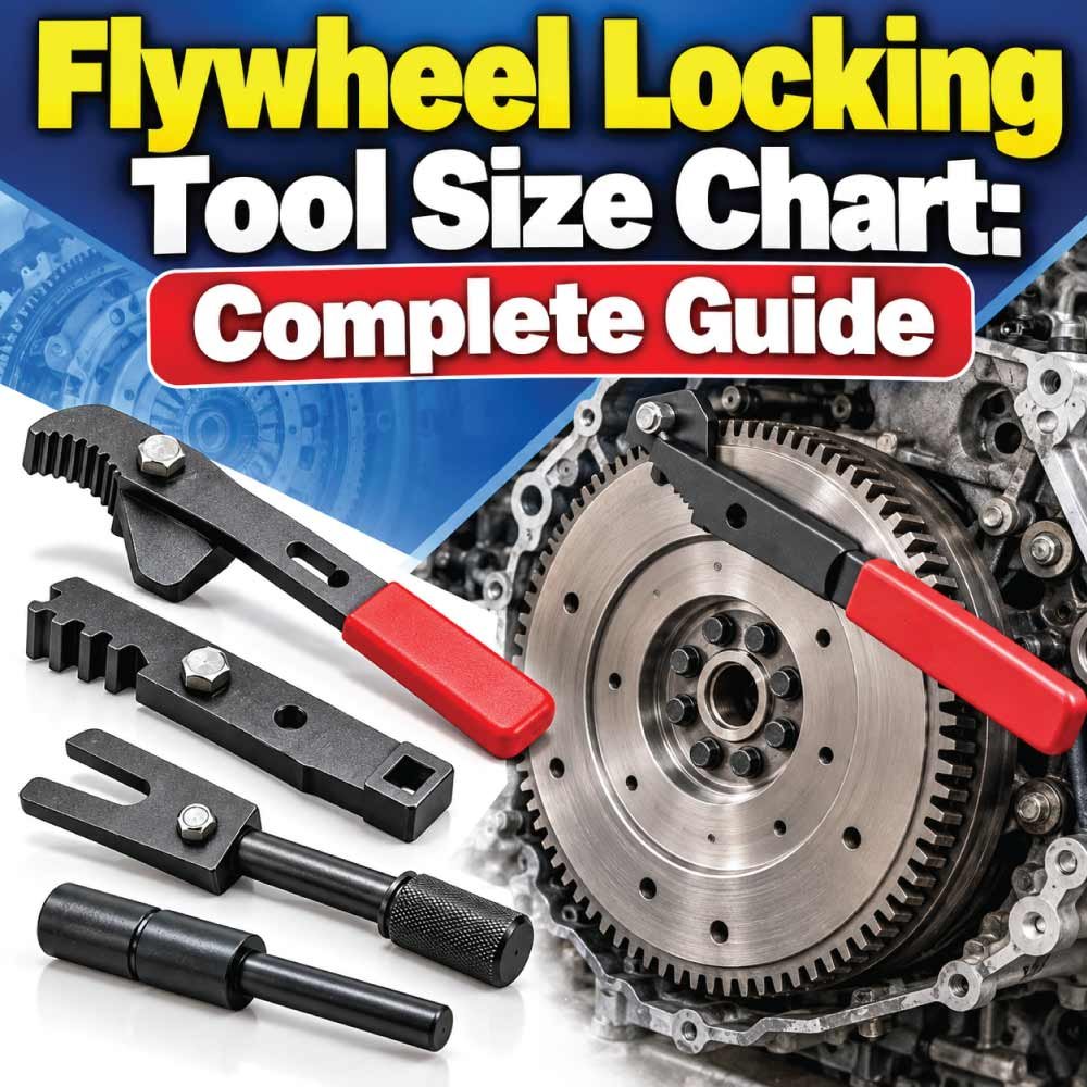
A flywheel locking tool holds an engine flywheel, flexplate, or related rotating assembly securely while you loosen or tighten high-torque fasteners. It is commonly used during clutch replacement, flywheel removal, crankshaft service, timing work, transmission repairs, and other engine jobs where the crankshaft must remain stationary.
Choosing the correct tool is not simply a matter of selecting the largest or smallest locking device. Flywheel diameter, starter-ring gear design, tooth profile, tooth spacing, mounting position, pin diameter, jaw range, and engine-specific fitment can all affect compatibility.
This flywheel locking tool size chart guide explains the important dimensions, common tool designs, measurement methods, selection factors, applications, and mistakes to avoid. Because there is no single universal flywheel locking tool size standard, exact dimensions should always be matched to the engine, flywheel, or tool manufacturer’s specifications.
What Is a Flywheel Locking Tool?
A flywheel locking tool is a mechanical device designed to prevent a flywheel or flexplate from rotating. The tool normally engages the flywheel’s starter-ring gear teeth, bolts to an engine or transmission mounting point, or uses another solid contact surface to restrain rotation.
During engine service, the crankshaft can rotate when torque is applied to a flywheel or crankshaft fastener. A locking tool provides a controlled mechanical stop instead of relying on transmission gear selection, improvised wedges, or another potentially unsuitable method.
Typical uses include:
- Removing and installing flywheel bolts
- Removing and installing clutch assemblies
- Holding a flexplate during torque converter work
- Crankshaft pulley service
- Engine timing procedures
- Flywheel inspection and replacement
- Transmission and clutch repairs
- Certain engine rebuilding operations
The correct tool should hold the rotating assembly firmly without damaging the ring gear teeth, flywheel surface, crankcase, or mounting point.
Flywheel Locking Tool Size Chart
Unlike socket sets, flywheel locking tools do not have one universal numbered size system. Manufacturers may identify tools by engine application, ring-gear tooth count, flywheel diameter, pin dimensions, mounting pattern, or adjustable capacity.
The following chart shows the principal dimensions that should be considered when selecting a tool.
| Dimension / Specification | What It Means | Why It Matters |
|---|---|---|
| Flywheel diameter | Outside diameter of the flywheel | Determines physical tool compatibility |
| Ring gear diameter | Diameter across the starter-ring gear | Important for tooth-engaging tools |
| Tooth count | Number of ring-gear teeth | Can identify engine or flywheel compatibility |
| Tooth pitch | Spacing between adjacent teeth | Must match the engaging mechanism |
| Tooth profile | Shape and form of the gear teeth | Prevents improper engagement |
| Pin diameter | Diameter of a locating or locking pin | Must fit the intended hole or feature |
| Pin spacing | Distance between mounting or locating pins | Important for multi-pin tools |
| Jaw capacity | Adjustable gripping range | Determines usable flywheel diameter range |
| Mounting-hole pattern | Location and spacing of mounting holes | Required for fixed-position tools |
| Tool reach | Distance from mounting point to engagement area | Ensures the tool can reach the flywheel |
| Engagement depth | Amount of tooth or surface contact | Affects secure holding |
| Material thickness | Thickness of the locking plate or arm | Affects rigidity and clearance |
These specifications are more useful than assigning an arbitrary “small,” “medium,” or “large” size to a flywheel locking tool.
How Flywheel Locking Tool Sizes Are Determined
The size of a locking tool generally relates to the physical geometry of the engine and flywheel rather than a universal tool-size designation.
Flywheel Diameter
Flywheel diameter is one of the first measurements to consider. Measure across the flywheel from one outer edge to the opposite outer edge.
For a ring-gear locking tool, the important diameter may instead be the diameter at which the starter-ring gear teeth are located.
Do not assume that two flywheels with the same outside diameter use the same locking tool. Their ring gear, tooth profile, mounting arrangement, and surrounding clearance may differ.
Ring Gear Tooth Count
The starter-ring gear is often a useful identification feature. Count the teeth when the manufacturer’s application information identifies compatibility by tooth count.
A different tooth count can indicate a different flywheel configuration, but tooth count alone does not guarantee compatibility.
Tooth Pitch and Profile
Two ring gears may have similar diameters while using different tooth geometry. A locking mechanism designed around one tooth profile may not properly engage another.
This is particularly important for tools that use a toothed hook, gear, or locking jaw.
Mounting Dimensions
Some flywheel holders attach directly to the engine block, bellhousing, transmission housing, or another fixed mounting location.
For these tools, measure:
- Mounting-hole diameter
- Center-to-center hole spacing
- Mounting position
- Tool reach
- Engagement location
- Available clearance
A tool can have the correct locking mechanism but still be unusable if its mounting holes or reach do not match the application.
Types of Flywheel Locking Tools
Different engine designs and repair procedures require different locking approaches.
Tooth-Engaging Flywheel Lock
A tooth-engaging tool uses a hook, pawl, pin, or shaped section that contacts the starter-ring gear.
Its main advantage is direct engagement with the flywheel assembly. However, the engagement geometry must match the ring gear correctly.
These tools are commonly useful when the flywheel has accessible starter-ring teeth and a suitable fixed mounting location is available.
Universal Adjustable Flywheel Holder
An adjustable holder can accommodate different flywheel diameters or tooth arrangements within its designed range.
These tools are useful for workshops servicing multiple engines because one tool may cover several applications.
However, “universal” does not mean every flywheel is compatible. The tool’s actual adjustment range, tooth engagement, mounting arrangement, and clearance must still be checked.
Flywheel Locking Plate
A locking plate typically attaches to an engine or transmission mounting point and extends toward the flywheel.
The plate may use a shaped tooth, pin, or stop that prevents rotation.
These tools are often compact and application-specific.
Flywheel Holding Tool
A flywheel holding tool may be designed primarily for installation and removal of flywheel fasteners rather than for a particular engine timing procedure.
The distinction is important because some tools are designed to hold the flywheel while applying torque, while others are designed for a specific locking position or service procedure.
Flexplate Locking Tool
Automatic transmissions commonly use a flexplate rather than a manual-transmission flywheel. A flexplate locking device is therefore designed around the available ring gear and engine/transmission geometry.
A tool intended for a heavy manual-transmission flywheel should not automatically be assumed suitable for a thinner flexplate.
How to Measure a Flywheel for a Locking Tool
Correct measurement is especially important when buying a tool without an application-specific part number.
Measure the Flywheel Diameter
Place the measuring instrument across the widest accessible portion of the flywheel.
For greater accuracy:
- Remove obstructions that prevent a straight measurement.
- Measure across the center where possible.
- Record the result in millimeters or inches.
- Measure again at another location to confirm consistency.
If the flywheel is installed, direct measurement may be difficult. In that case, manufacturer specifications or the original flywheel identification may be more reliable.
Measure the Ring Gear
For a tooth-engaging locking tool, identify the starter-ring gear.
Record:
- Outside diameter of the ring gear
- Tooth count
- Tooth shape
- Tooth spacing
- Width of the gear
- Available engagement depth
Avoid forcing a measuring tool into the teeth because damaged or worn teeth can produce misleading measurements.
Measure Mounting Holes
If the tool bolts to the engine or transmission housing, measure the mounting pattern.
Important dimensions include:
- Hole diameter
- Center-to-center distance
- Number of holes
- Hole arrangement
- Distance from mounting holes to the flywheel
- Available surrounding clearance
These dimensions can be more important than flywheel diameter for a fixed locking plate.
Important Flywheel Locking Tool Dimensions
Several dimensions determine whether a tool can physically reach and restrain the flywheel.
Jaw or Arm Range
Adjustable tools have a working range. The flywheel or ring gear must fall inside that range while still allowing sufficient engagement.
Do not select a tool based only on its maximum opening. Check the minimum and maximum working range.
Engagement Depth
The locking component needs enough contact with the flywheel or ring gear to prevent movement.
Insufficient engagement can allow the tool to slip, while excessive engagement may cause interference with the flywheel, housing, or other components.
Tool Reach
The distance between the mounting point and locking mechanism determines whether the tool can reach the correct position.
A tool can have the correct tooth compatibility and still fail because its arm is too short or the surrounding components interfere.
Clearance
Clearance is frequently overlooked.
Check the space around:
- Starter motor openings
- Bellhousing edges
- Engine block surfaces
- Flywheel bolts
- Clutch components
- Transmission housing
- Wiring and sensors
- Adjacent rotating components
A correctly sized tool should sit securely without contacting components that it is not designed to touch.
Flywheel Locking Tool Selection Guide
Selecting the correct tool becomes easier when the application is identified first.
| Selection Factor | What to Check | Best Approach |
|---|---|---|
| Engine application | Engine make, model, and configuration | Start with application-specific compatibility |
| Flywheel type | Manual flywheel or flexplate | Select the appropriate tool type |
| Ring gear | Tooth count and profile | Match the engagement mechanism |
| Diameter | Flywheel/ring gear dimensions | Confirm the tool’s working range |
| Mounting | Bolt holes or fixed location | Compare mounting dimensions |
| Clearance | Available installation space | Verify physical fit |
| Torque requirement | Fastener being serviced | Use a sufficiently rigid locking method |
| Tool material | Plate, arm, pin, or jaw construction | Prefer suitable heavy-duty construction |
| Application coverage | Single or multiple engines | Choose dedicated or adjustable design |
For professional work, an application-specific tool can simplify compatibility because its intended engine or flywheel application is already defined.
Also Read:
Why There Is No Universal Flywheel Locking Tool Size
Searches for a single “flywheel locking tool size” can be confusing because manufacturers use different sizing systems.
Some tools are identified by:
- Vehicle application
- Engine family
- Flywheel part number
- Ring-gear tooth count
- Diameter range
- Mounting pattern
- Tool model number
- Pin dimensions
As a result, a tool described as “large” by one manufacturer may not correspond to a similarly described tool from another manufacturer.
The most reliable approach is to match the actual dimensions and application, not simply the name of the size.
Flywheel Locking Tool vs. Flywheel Holder
The terms “flywheel locking tool” and “flywheel holder” are sometimes used interchangeably, but their intended use can differ.
A locking tool generally prevents rotation by engaging a fixed feature or gear. A holding tool may provide a handle or rigid structure that allows the technician to restrain the flywheel while working on fasteners.
The distinction matters because a tool designed for light holding may not be intended for every high-torque application.
Before using one, check:
- Intended engine application
- Maximum recommended load or torque, if specified
- Mounting method
- Engagement method
- Material and construction
- Manufacturer’s service instructions
How to Use a Flywheel Locking Tool
Once the correct tool has been selected, installation should be performed carefully.
Basic Installation Procedure
- Turn the engine off and make the work area safe.
- Access the flywheel or flexplate according to the applicable service procedure.
- Identify a suitable engagement point on the ring gear or flywheel.
- Position the locking tool against the intended fixed mounting location.
- Engage the teeth or locking surface completely.
- Secure the tool firmly using the appropriate mounting hardware.
- Check for movement before applying torque.
- Perform the required service operation.
- Remove the locking tool only after the rotating assembly is no longer required to remain stationary.
Never use a locking tool that is visibly bent, cracked, excessively worn, or unable to maintain secure engagement.
Also Read:
Common Applications for Flywheel Locking Tools
Flywheel locking devices are useful in many engine repair procedures.
Clutch Replacement
During manual-transmission clutch work, the flywheel must remain stationary while fasteners are loosened or tightened.
A suitable locking tool provides a stable mechanical restraint.
Flywheel Replacement
Flywheel bolts can require substantial tightening force. The locking device prevents the crankshaft from rotating while torque is applied.
Crankshaft Service
Some crankshaft pulley and front-end procedures require the crankshaft to remain stationary. Whether a flywheel lock is appropriate depends on the engine manufacturer’s service procedure.
Timing Work
Certain engine designs use the flywheel or flexplate as a reference or locking location during timing procedures.
Always follow the engine-specific procedure because the correct locking position can vary considerably.
Transmission-Related Repairs
During transmission removal or installation, the flywheel or flexplate may need to be restrained for specific service operations.
Common Mistakes When Choosing a Flywheel Locking Tool
A wrong tool can damage the tool itself or the engine component it contacts.
Choosing by Diameter Alone
Flywheel diameter is useful, but it is not enough.
Two flywheels with similar diameters may have different tooth counts, tooth profiles, mounting arrangements, or clearance requirements.
Ignoring Tooth Geometry
A locking hook that only partially engages the ring gear can slip under load.
Check tooth engagement rather than assuming that similar-looking gears are compatible.
Using an Improvised Lock
Screwdrivers, pry bars, loose bolts, or other improvised objects can damage ring-gear teeth or nearby components.
A purpose-designed locking device provides controlled engagement and is generally more appropriate for service work.
Ignoring Clearance
A tool that technically reaches the flywheel may interfere with the bellhousing, starter, sensors, or other parts.
Always check the complete installation position.
Applying Excessive Force to the Tool
A locking tool is intended to restrain rotation within its designed application. It should not be treated as an unlimited-strength substitute for an appropriate service fixture.
Also Read:
How to Tell if the Flywheel Locking Tool Fits
Before applying torque, inspect the installed tool.
A properly fitted tool should:
- Sit firmly against its mounting surface
- Engage the flywheel or ring gear securely
- Maintain full intended contact
- Avoid unstable or angled engagement
- Have adequate clearance
- Remain stationary when moderate force is applied
- Not contact unrelated engine components
If the tool moves, rocks, slips, or contacts an unintended component, stop and reassess the fit.
Flywheel Locking Tool Size Chart: Quick Reference
The following reference summarizes the measurements that matter most when researching a replacement or universal locking tool.
| Measurement | Measure On | Purpose |
|---|---|---|
| Overall diameter | Flywheel | Establishes general physical size |
| Ring-gear diameter | Starter ring gear | Determines gear engagement location |
| Tooth count | Ring gear | Helps identify compatibility |
| Tooth pitch | Adjacent ring-gear teeth | Confirms engagement geometry |
| Tooth width | Ring gear | Checks contact area |
| Pin diameter | Tool or flywheel feature | Confirms pin fit |
| Hole diameter | Mounting location | Confirms fastening compatibility |
| Hole spacing | Mounting pattern | Confirms tool alignment |
| Reach | Locking tool | Confirms access to engagement point |
| Clearance | Installation area | Prevents interference |
This is a measurement reference rather than a universal dimensional standard. Exact values depend on the engine and flywheel assembly being serviced.
Choosing Between Universal and Application-Specific Tools
A universal tool can be practical for a workshop that services many different engines. Its adjustable design may cover several flywheel diameters or engagement configurations.
An application-specific tool, however, is generally easier to match when the exact engine is known because the tool is designed around a particular mounting arrangement or flywheel configuration.
Consider a universal design when:
- You service multiple engine types.
- The adjustment range covers your application.
- The engagement mechanism matches the ring gear.
- The mounting arrangement is compatible.
Consider an application-specific design when:
- The engine has unusual flywheel geometry.
- Clearance is limited.
- The service procedure specifies a particular locking fixture.
- A precise fit is required.
The key is verified compatibility, rather than assuming that a tool labeled universal will fit every engine.
Maintenance and Inspection of Flywheel Locking Tools
A locking tool should be inspected before each demanding application.
Look for:
- Bent arms
- Cracked plates
- Damaged teeth or hooks
- Worn pins
- Elongated mounting holes
- Loose adjustment hardware
- Corrosion that affects structural integrity
- Deformed contact surfaces
Keep the tool clean so that dirt or metal debris does not prevent proper engagement.
If an adjustable tool develops excessive play, inspect its adjustment mechanism before using it again. A loose locking mechanism can reduce engagement and create an unsafe working condition.
Frequently Asked Questions
Are flywheel locking tools universal?
Some are adjustable and marketed for multiple applications, but there is no guarantee that one tool fits every flywheel. Compatibility depends on dimensions, tooth geometry, mounting location, and available clearance.
How do I know what size flywheel locking tool I need?
Start with the engine and flywheel application. Then check flywheel diameter, ring-gear tooth count and profile, mounting dimensions, tool reach, and clearance against the manufacturer’s compatibility information.
Does flywheel diameter determine the tool size?
It can be an important factor, particularly for adjustable tools, but diameter alone does not determine compatibility. Tooth geometry and mounting arrangement may be equally important.
Can a flywheel locking tool be used on a flexplate?
Some tools are designed for both applications, while others are intended specifically for a flywheel or flexplate. Check the tool’s stated application before use.
Should I measure the flywheel or ring gear?
For a tooth-engaging tool, the ring gear is particularly important because the locking mechanism interacts with its teeth. Depending on the tool design, flywheel diameter and mounting dimensions may also be necessary.
Can I use a locking tool with damaged ring-gear teeth?
Damaged teeth can prevent proper engagement. If the tool cannot achieve secure contact, it should not be forced into position. The damaged component and the appropriate service procedure should be evaluated first.
Is tooth count enough to identify a locking tool?
No. Tooth count can help identify compatibility, but tooth profile, pitch, diameter, mounting arrangement, and tool geometry may also be required.
What is the most important dimension?
There is no single dimension that applies to every design. For tooth-engaging tools, ring-gear geometry is critical. For fixed mounting tools, mounting pattern and reach may be equally important.
Final Takeaway
A Flywheel Locking Tool Size Chart should be treated as a guide to the measurements that determine compatibility rather than as one universal list of tool sizes. Flywheel diameter, ring-gear diameter, tooth count, tooth profile, mounting holes, pin dimensions, engagement depth, reach, and clearance all influence the correct choice.
For reliable selection, identify the exact engine and flywheel or flexplate first, then compare its dimensions with the locking tool’s specified application and working range. When exact fitment is uncertain, manufacturer documentation and the applicable engine service procedure should take priority over assumptions based on appearance or nominal size.

Engineer Hassan is a Mechanical Engineer with 16+ years of hands-on experience in mechanical hardware, fasteners, and workshop tools. He focuses on size selection, thread identification, and measurement, helping users choose the correct components with accuracy and safety.