Flanges are essential components used in piping systems, industrial plants, plumbing, oil and gas facilities, water treatment systems, and mechanical equipment. They connect pipes, valves, pumps, and other equipment securely while allowing easy maintenance and disassembly.
Choosing the correct flange size is extremely important because improper sizing can lead to leaks, pressure loss, equipment failure, and safety hazards.
In this detailed guide, you will learn everything about flange sizes, dimensions, pressure classes, standards, and applications. You will also find a complete flange size chart to help identify the correct flange quickly.
What Is a Flange?
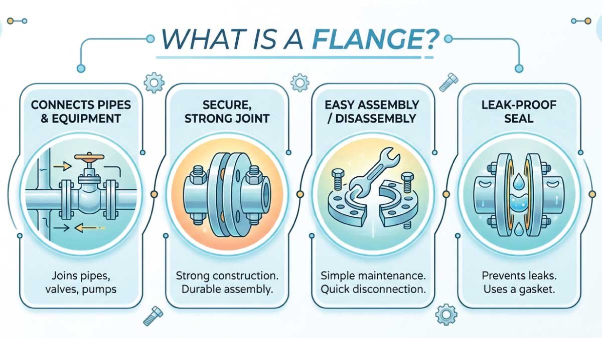
A flange is a raised rim or collar used to connect pipes, valves, pumps, and other equipment in a piping system. It provides a strong, secure joint that can be easily assembled or disassembled. Flanges are typically bolted together with a gasket between them to ensure a tight, leak-proof seal.
Flanges are commonly used in:
- Oil and gas pipelines
- Water supply systems
- Chemical plants
- Power generation
- HVAC systems
- Industrial machinery
Most flanges are made from:
- Carbon steel
- Stainless steel
- Cast iron
- Brass
- PVC
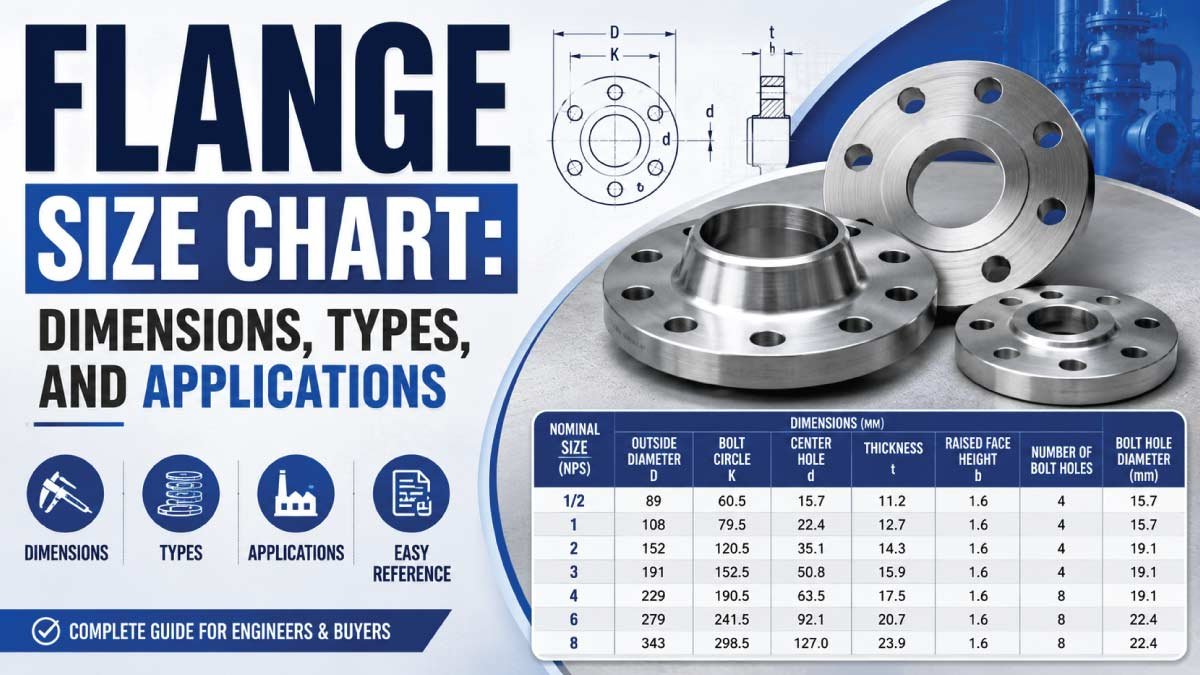
Understand The Flange Measurements
Before using a flange size chart, it is important to understand the basic flange dimensions. These measurements help ensure proper fitting, correct alignment, and a secure leak-proof connection between pipes and equipment in industrial piping systems.
1. Nominal Pipe Size (NPS)
Nominal Pipe Size (NPS) refers to the standard pipe size that a flange is designed to fit. It is not the exact measurement but a reference size used in piping systems. Correct NPS selection ensures proper compatibility between the pipe and flange connection.
Examples:
- 1 inch
- 2 inch
- 4 inch
- 6 inch
Larger industrial systems may use flanges above 24 inches for heavy-duty applications.
2. Outside Diameter (OD)
The outside diameter is the total width of the flange measured from one outer edge to the other. It determines the overall size of the flange and helps ensure proper fitting with connected components and supporting structures.
3. Bolt Circle Diameter (BCD)
Bolt Circle Diameter (BCD), also known as pitch circle diameter, is the diameter of the circle that passes through the center of all bolt holes. This measurement is critical for aligning bolts correctly during installation and ensuring a tight, even seal.
4. Number of Bolt Holes
The number of bolt holes varies depending on flange size and pressure rating. Higher pressure applications generally require more bolts to ensure stronger tightening and better sealing performance under stress and vibration.
5. Flange Thickness
Flange thickness refers to the distance between the front and back faces of the flange. Thicker flanges are used in high-pressure systems because they provide greater strength, durability, and resistance to deformation during operation.
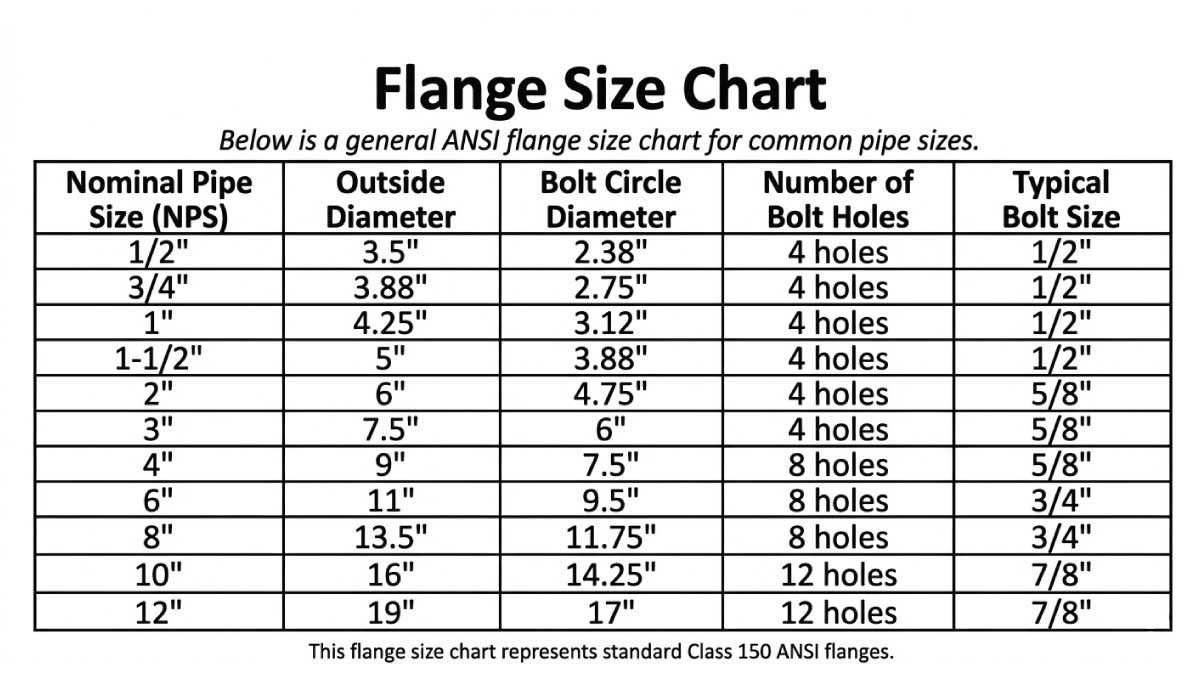
Flange Size Chart
Below is a general ANSI flange size chart for common pipe sizes. This chart is commonly used for reference when selecting Class 150 flanges in piping systems. It helps ensure proper matching between pipe size, bolt pattern, and flange dimensions for safe and leak-free connections.
| Nominal Pipe Size (NPS) | Outside Diameter | Bolt Circle Diameter | Number of Bolt Holes | Typical Bolt Size |
|---|---|---|---|---|
| 1/2″ | 3.5″ | 2.38″ | 4 | 1/2″ |
| 3/4″ | 3.88″ | 2.75″ | 4 | 1/2″ |
| 1″ | 4.25″ | 3.12″ | 4 | 1/2″ |
| 1-1/2″ | 5″ | 3.88″ | 4 | 1/2″ |
| 2″ | 6″ | 4.75″ | 4 | 5/8″ |
| 3″ | 7.5″ | 6″ | 4 | 5/8″ |
| 4″ | 9″ | 7.5″ | 8 | 5/8″ |
| 6″ | 11″ | 9.5″ | 8 | 3/4″ |
| 8″ | 13.5″ | 11.75″ | 8 | 3/4″ |
| 10″ | 16″ | 14.25″ | 12 | 7/8″ |
| 12″ | 19″ | 17″ | 12 | 7/8″ |
This flange size chart represents standard Class 150 ANSI flanges.
Flange Size Chart Image
Flange Size Chart PDF
Flange Size Chart PDF is a detailed reference guide showing standard flange dimensions, including outer diameter, bolt circle, bolt size, and thickness. It helps engineers, plumbers, and technicians select the correct flange for piping systems. This downloadable PDF ensures accurate fitting, leak-free connections, and reliable performance in industrial applications.
Common Flange Types
Different piping systems use different flange types depending on pressure, temperature, installation method, and maintenance needs. Each flange design offers specific advantages for strength, sealing performance, and ease of assembly in industrial and mechanical applications.
1. Weld Neck Flange
A weld neck flange has a long tapered hub that is welded directly to the pipe, creating a strong and continuous connection. It is designed to reduce stress concentration at the base and provide excellent structural strength under high-pressure conditions.
Advantages
- Excellent strength
- High pressure resistance
- Good stress distribution
Common Uses
- High-pressure systems
- Oil and gas pipelines
- Steam systems
2. Slip-On Flange
Slip-on flanges are designed to slide over the pipe before being welded both inside and outside. This makes installation easier and faster compared to other flange types. They are widely used where moderate pressure and cost-effective solutions are required.
Advantages
- Easy installation
- Lower cost
- Good alignment
Common Uses
- Low-pressure piping
- Water systems
3. Blind Flange
A blind flange is a solid disk used to completely seal the end of a piping system. It does not allow flow and is mainly used for closing pipe ends during maintenance, testing, or future system expansion.
Applications
- Maintenance shutdowns
- Future pipeline expansion
- Pressure testing
4. Socket Weld Flange
Socket weld flanges are designed for small-diameter, high-pressure piping systems. The pipe is inserted into a socket and then welded internally, creating a strong and leak-resistant connection suitable for compact piping layouts.
Features
- Pipe inserts into socket
- Internal weld connection
Common Uses
- Hydraulic systems
- Steam lines
5. Threaded Flange
Threaded flanges use internal threads instead of welding, allowing pipes to be screwed directly into the flange. This makes them ideal for applications where welding is not possible or where future disassembly is required.
Advantages
- Easy assembly
- No welding required
Common Uses
- Low-pressure systems
- Hazardous environments where welding is risky
6. Lap Joint Flange
Lap joint flanges are used with a stub end and are designed for systems that require frequent dismantling. The flange itself is not welded to the pipe, making it reusable and easy to align during installation.
Advantages
- Easy alignment
- Reusable backing flange
Read This Latest guide:
Flange Pressure Classes
Flanges are classified according to their pressure-handling capacity. These pressure classes help engineers select the correct flange for safe operation under specific temperature and pressure conditions. Higher pressure ratings require stronger materials and more robust designs to prevent leakage or failure.
| Pressure Class | Typical Applications |
|---|---|
| Class 150 | Low-pressure systems |
| Class 300 | Medium pressure |
| Class 600 | High-pressure piping |
| Class 900 | Very high pressure |
| Class 1500 | Extreme pressure |
| Class 2500 | Heavy industrial systems |
Higher pressure classes generally require:
- Thicker flanges
- Larger bolts
- Stronger materials
ANSI Flange Standards
Most industrial flange systems follow standardized guidelines to ensure compatibility, safety, and interchangeability. ANSI and ASME standards define the key design and manufacturing requirements for flanges used in piping systems worldwide.
Common Standards
- ASME B16.5
- ASME B16.47
These standards define:
- Dimensions
- Pressure ratings
- Bolt patterns
- Materials
Following these standards ensures that flanges from different manufacturers can work together safely and efficiently in industrial systems.
Metric Flange Size Chart
Some countries and industries use metric-based flange sizing instead of imperial units. The DN (Diameter Nominal) system is commonly used to represent approximate pipe size equivalents in millimeters.
| DN Size | Approximate NPS Equivalent |
|---|---|
| DN15 | 1/2″ |
| DN20 | 3/4″ |
| DN25 | 1″ |
| DN40 | 1-1/2″ |
| DN50 | 2″ |
| DN80 | 3″ |
| DN100 | 4″ |
| DN150 | 6″ |
| DN200 | 8″ |
DN stands for “Diameter Nominal,” which is a standard reference used to indicate pipe and flange sizes in metric systems.
Flange Face Types
The flange face type plays an important role in sealing performance, leakage prevention, and pressure handling capability. Different face designs are used depending on system pressure, temperature, and fluid type to ensure a strong and reliable joint between connected components.
1. Raised Face (RF)
Raised face flanges are the most commonly used flange face type in industrial piping systems. They feature a slightly raised circular area around the bore, which helps concentrate pressure on the gasket for better sealing efficiency and reliability.
Advantages
- Better gasket compression
- Improved sealing performance
2. Flat Face (FF)
Flat face flanges have a completely flat sealing surface with no raised section. They are mainly used in low-pressure applications where minimal stress is applied to the flange connection. These flanges are often used with cast iron equipment to prevent cracking.
Common Features
- Flat sealing surface
- Even pressure distribution across the gasket
Common Uses
- Low-pressure systems
- Cast iron piping systems
3. Ring Type Joint (RTJ)
Ring Type Joint flanges are designed for high-pressure and high-temperature environments where maximum sealing reliability is required. They use a metal ring gasket that sits in a specially machined groove, creating a tight metal-to-metal seal.
Advantages
- Superior sealing performance
- Suitable for extreme pressure and temperature conditions
Common Uses
- Oil and gas industry
- High-pressure pipelines
- Petrochemical plants
Read This Latest guide:
Male and Female Flanges
Male and female flanges are a special type of flange face design used to improve alignment accuracy and sealing performance in piping systems. One flange has a raised (male) face, while the other has a matching recessed (female) face, allowing them to fit together precisely.
This design helps reduce gasket movement and improves sealing efficiency, especially in systems where proper alignment is critical for preventing leakage.
Common Features
- Precise alignment between flange faces
- Improved gasket positioning
- Better sealing reliability
Advantages
- Reduces misalignment during installation
- Enhances leak-proof performance
- Provides stable connection under pressure
Common Uses
- Specialized industrial piping systems
- High-precision fluid handling systems
- Equipment requiring accurate flange alignment
Flange Materials
Flange material selection is very important because it directly affects strength, durability, corrosion resistance, and performance under different pressure and temperature conditions. Choosing the right material ensures long service life and safe operation in industrial piping systems.
1. Carbon Steel Flanges
Carbon steel is the most widely used material for flanges in industrial applications. It offers a strong balance of durability, strength, and cost-effectiveness, making it suitable for general-purpose piping systems where extreme corrosion resistance is not required.
Advantages
- Strong
- Affordable
- Durable
2. Stainless Steel Flanges
Stainless steel flanges are highly resistant to corrosion, rust, and chemical damage. They are preferred in environments where hygiene, moisture, or aggressive chemicals are present. These flanges maintain performance even in harsh and demanding conditions.
Used in
- Food processing
- Chemical plants
- Marine systems
3. Cast Iron Flanges
Cast iron flanges are commonly used in water supply and drainage systems. They offer good strength for low to medium pressure applications but are not suitable for high-pressure or high-temperature environments due to their brittle nature.
Common Uses
- Water systems
- Drainage systems
4. PVC Flanges
PVC flanges are used in plastic piping systems where corrosion resistance and lightweight handling are important. They are easy to install and are ideal for low-pressure applications involving water and non-aggressive fluids.
Advantages
- Lightweight
- Corrosion resistant
Read This Latest guide:
How to Measure a Flange
Proper flange measurement is important for correct fitting, replacement, and system compatibility. Accurate dimensions help ensure leak-free connections and safe operation in piping systems used in industrial, mechanical, and plumbing applications.
1. Measure Pipe Size
The first step is to identify the nominal pipe size (NPS). This helps determine the basic compatibility between the flange and the pipe. Pipe size is usually standard and must match the flange specification for proper installation.
2. Measure Outside Diameter
Measure the outer edge of the flange across its widest point. This outside diameter is important for checking whether the flange will fit correctly within the available space and align properly with connected components.
3. Count Bolt Holes
Count the total number of bolt holes present on the flange. The number of holes varies depending on flange type and pressure class. This helps ensure proper bolting alignment with the mating flange or equipment.
4. Measure Bolt Circle Diameter
Measure the bolt circle diameter (BCD) by taking the distance from the center of one bolt hole to the center of the opposite hole. This measurement ensures correct bolt alignment and proper sealing between flange connections.
5. Measure Flange Thickness
Measure the thickness of the flange body from one flat face to the other. This dimension is important for determining strength and pressure rating, as thicker flanges are generally used for higher pressure and heavy-duty applications.
Flange Bolt Size Chart
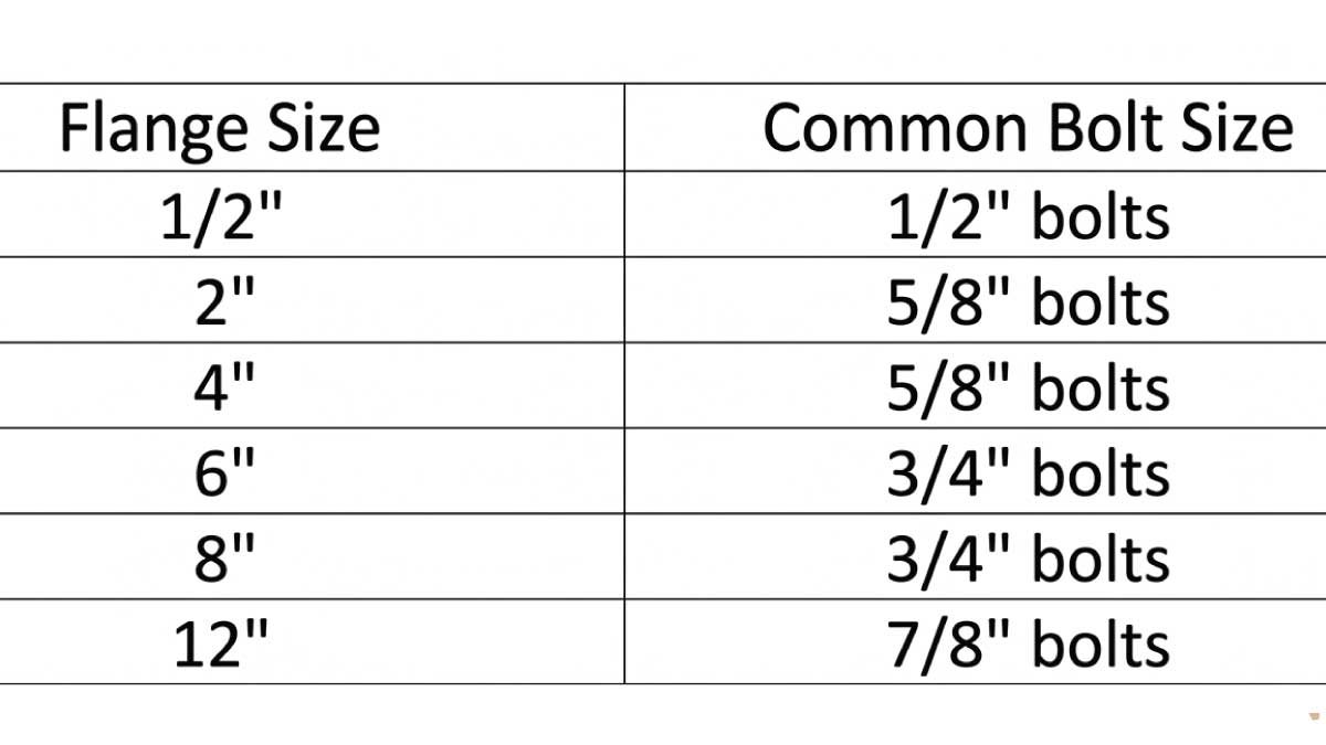
Bolt sizes vary by flange size and pressure class.
| Flange Size | Common Bolt Size |
|---|---|
| 1/2″ | 1/2″ bolts |
| 2″ | 5/8″ bolts |
| 4″ | 5/8″ bolts |
| 6″ | 3/4″ bolts |
| 8″ | 3/4″ bolts |
| 12″ | 7/8″ bolts |
Always follow flange standard specifications.
Common Flange Applications
Flanges are widely used in different industries to connect pipes, valves, pumps, and other equipment. They provide strong, leak-proof joints and make system maintenance, inspection, and replacement much easier in industrial piping networks.
1. Oil and Gas Industry
In the oil and gas industry, flanges are used for high-pressure pipeline connections. They ensure safe transport of oil, gas, and petroleum products by providing strong sealing and reliable joint strength under extreme pressure and temperature conditions.
2. Water Treatment Plants
Flanges are commonly used in water treatment facilities to connect pumps, pipes, and valves. They help maintain smooth water flow, support system flexibility, and allow easy maintenance or replacement of components without disrupting the entire pipeline system.
3. HVAC Systems
In HVAC (Heating, Ventilation, and Air Conditioning) systems, flanges are used in chilled water lines and heating networks. They help connect ducting and piping sections securely while ensuring efficient fluid flow and system stability in temperature control applications.
4. Chemical Processing
Chemical industries use flanges made from corrosion-resistant materials to handle aggressive chemicals. These flanges prevent leaks and withstand chemical reactions, ensuring safety, durability, and long service life in highly corrosive processing environments.
5. Marine Systems
In marine applications, stainless steel flanges are commonly used because they resist saltwater corrosion. They are ideal for shipbuilding, offshore platforms, and seawater systems where durability, strength, and corrosion resistance are essential for long-term performance.
Advantages of Flanges
Flanges provide many practical benefits in piping and industrial systems. They are widely used because they offer strong connections, easy maintenance, and reliable sealing performance in both low and high-pressure applications.
1. Easy Maintenance
Flanged systems are easy to assemble and disassemble, making maintenance simple and efficient. Components can be removed or replaced without cutting pipes, which reduces downtime and makes inspection and repair work much faster and more convenient.
2. Strong Connections
Flanges create strong and secure joints that are suitable for high-pressure piping systems. When properly bolted and sealed, they provide excellent structural strength and stability, ensuring safe operation in demanding industrial environments such as oil, gas, and chemical plants.
3. Versatility
Flanges are available in a wide range of sizes, pressure ratings, and materials. This versatility allows them to be used in many industries and applications, from water pipelines to heavy industrial systems, making them a flexible piping solution.
4. Leak Prevention
Flanges use gaskets between mating surfaces to create a tight seal. When correctly installed, this sealing system significantly reduces the risk of leaks, ensuring safe fluid or gas transport and improving the overall reliability of the piping network.
Common Flange Problems
Flange systems can develop issues if they are not installed correctly or if they operate in unsuitable conditions. These problems can lead to leakage, reduced efficiency, and even system failure if not addressed in time. Proper installation, maintenance, and material selection are essential to avoid these issues.
1. Leaks
Leakage is one of the most common flange problems and usually occurs due to improper sealing or installation errors. Even a small gap can allow fluid or gas to escape, affecting system performance and safety.
Usually caused by:
- Incorrect gasket installation
- Uneven bolt tightening
- Damaged flange faces
2. Corrosion
Corrosion occurs when flanges are exposed to moisture, chemicals, or harsh environmental conditions without proper protection. It weakens the material over time and can lead to surface damage, leaks, or complete flange failure if not controlled.
3. Misalignment
Misalignment happens when flanges are not properly aligned during installation. This creates uneven stress on bolts and gasket surfaces, increasing the risk of leakage and mechanical strain on the piping system. Proper alignment is necessary to ensure a stable and secure connection.
Flange Installation Tips
Proper flange installation is essential for ensuring safe operation, leak prevention, and long-term reliability of piping systems. Following correct procedures helps maintain strong sealing performance and reduces the risk of system failure.
1. Use Proper Gaskets
Select a gasket material that matches the operating pressure, temperature, and fluid type. The correct gasket ensures a tight seal between flange faces, preventing leaks and improving system safety and durability under working conditions.
2. Tighten Bolts Evenly
Bolts should be tightened using a crisscross or star pattern. This ensures even pressure distribution across the flange face, preventing distortion, uneven sealing, and potential leakage during system operation.
3. Inspect Flange Faces
Before installation, carefully inspect the flange surfaces to ensure they are clean, smooth, and free from dirt, rust, or damage. Proper surface condition is critical for achieving an effective seal and preventing leakage issues.
4. Follow Torque Specifications
Always apply the recommended torque values when tightening flange bolts. Over-tightening can damage the gasket, bolts, or flange surface, while under-tightening may cause leaks. Correct torque ensures safe, reliable, and long-lasting connections.
Final Thoughts
Understanding flange sizes is essential for safe and efficient piping system installation. Whether working in plumbing, industrial maintenance, oil and gas, or HVAC systems, selecting the correct flange size and pressure class helps prevent leaks and system failures.
A flange size chart makes it easier to identify dimensions, bolt patterns, and compatible pipe sizes. Weld neck, slip-on, blind, threaded, and socket weld flanges each serve different purposes depending on pressure requirements and installation methods.
By following proper measurement techniques, using the correct materials, and applying proper installation practices, flanges can provide reliable long-term performance in both low-pressure and high-pressure systems.
FAQs:
What Is the Most Common Flange Type?
The raised face weld neck flange is one of the most widely used flange types in industrial applications. It provides strong reinforcement, excellent sealing capability, and is commonly used in high-pressure and high-temperature piping systems.
What Does Class 150 Mean?
Class 150 refers to a flange pressure rating category defined by industry standards. It indicates the maximum pressure the flange can safely handle at a specific temperature. Higher classes such as 300, 600, or above are designed for higher pressure applications.
How Do I Identify Flange Size?
Flange size can be identified by measuring key dimensions such as pipe size (NPS), outside diameter, bolt circle diameter, and the number of bolt holes. These measurements help ensure correct matching with piping and equipment connections.
What Is the Difference Between NPS and DN?
NPS (Nominal Pipe Size) is based on the imperial system and uses inches, while DN (Diameter Nominal) follows the metric system. Both represent nominal pipe sizing standards used to describe pipe and flange compatibility.
Are Flanges Reusable?
Yes, flanges can often be reused if they are not damaged, deformed, or heavily corroded. However, gaskets should generally be replaced during reassembly to ensure proper sealing and prevent leaks in the system.

Engineer Hassan is a Mechanical Engineer with 16+ years of hands-on experience in mechanical hardware, fasteners, and workshop tools. He focuses on size selection, thread identification, and measurement, helping users choose the correct components with accuracy and safety.