
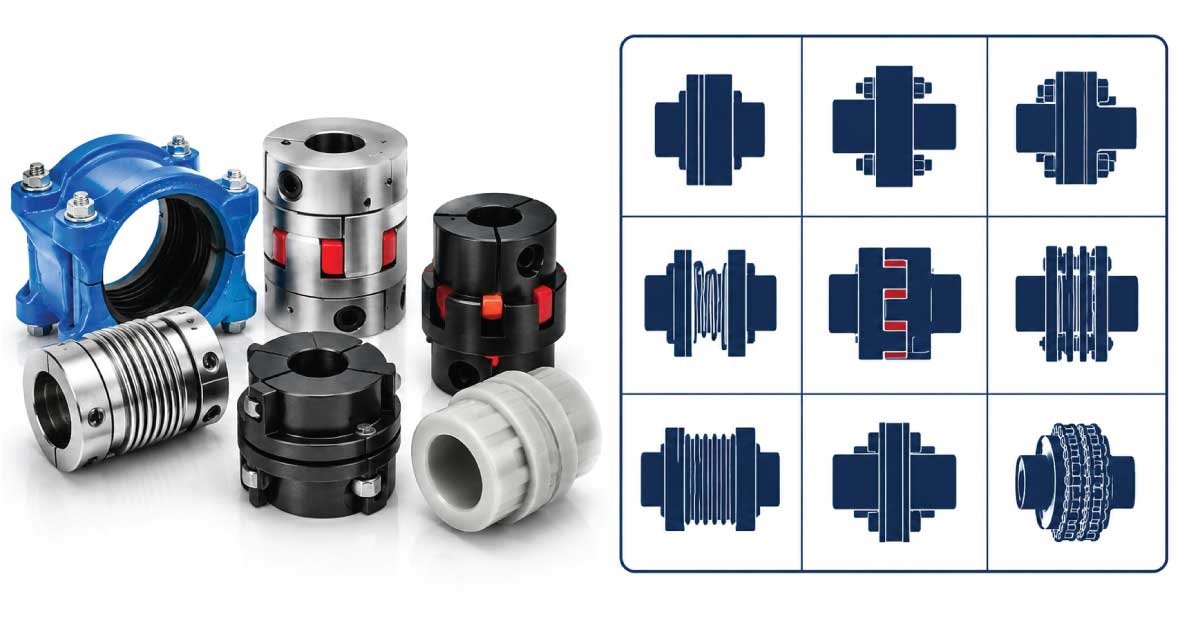
Couplings are essential mechanical components used to connect two rotating shafts for transmitting torque and power efficiently. Whether in industrial machinery, pumps, compressors, conveyors, or automotive systems, selecting the correct coupling size ensures reliable performance, minimizes vibration, reduces wear, and extends equipment life.
This complete guide explains coupling sizes, dimensions, standards, types, and measurement methods with practical examples and detailed size charts suitable for beginners, mechanics, engineers, and maintenance professionals.
What Is a Coupling?
A coupling is a mechanical device designed to join two shafts together for transmitting rotational power while accommodating slight misalignment, vibration, thermal expansion, or shaft movement. Proper coupling selection improves machinery efficiency, protects connected equipment from excessive stress, and reduces maintenance costs across numerous industrial applications.
A coupling transfers torque from the driving shaft to the driven shaft while maintaining smooth operation. Depending on the application, couplings may be rigid or flexible and are available in numerous sizes and materials.
Common applications include:
- Electric motors
- Industrial pumps
- Gearboxes
- Compressors
- Conveyor systems
- Agricultural equipment
- HVAC systems
- Marine machinery
- Manufacturing equipment
- Mining machinery
Selecting the appropriate coupling size is one of the most important steps in designing a dependable power transmission system.
Why Coupling Size Matters
The correct coupling size directly affects torque transmission, shaft alignment, vibration control, equipment reliability, and overall operating efficiency. An undersized coupling may fail prematurely under heavy loads, while an oversized coupling can increase installation costs and reduce system performance. Understanding proper sizing helps ensure long-term reliability and safe machine operation.
Incorrect coupling sizing may lead to:
- Excessive vibration
- Shaft misalignment
- Premature bearing failure
- Increased maintenance
- Reduced equipment efficiency
- Unexpected downtime
- Higher operating costs
Proper sizing provides:
- Efficient power transmission
- Longer service life
- Reduced mechanical stress
- Better alignment compensation
- Lower maintenance requirements
Coupling Size Chart
The following chart provides typical dimensions and torque capacities for common flexible shaft couplings. Actual specifications may vary slightly between manufacturers, so always verify product data before installation.
| Coupling Size | Shaft Bore Range (mm) | Outside Diameter (mm) | Overall Length (mm) | Maximum Torque (Nm) | Typical Application |
|---|---|---|---|---|---|
| 19 | 6–10 | 19 | 25 | 8 | Small motors |
| 24 | 8–12 | 24 | 30 | 18 | Pumps |
| 28 | 10–14 | 28 | 35 | 30 | Light machinery |
| 38 | 12–20 | 38 | 45 | 75 | Conveyors |
| 42 | 14–22 | 42 | 54 | 110 | Gear drives |
| 48 | 18–28 | 48 | 62 | 180 | Compressors |
| 55 | 20–32 | 55 | 78 | 260 | Industrial equipment |
| 65 | 25–38 | 65 | 90 | 420 | Heavy-duty drives |
| 75 | 30–45 | 75 | 105 | 650 | Manufacturing machinery |
| 90 | 35–55 | 90 | 125 | 1,000 | Large industrial systems |
Always consult the manufacturer’s catalog for exact dimensions and performance ratings.
Understanding Coupling Dimensions
Every coupling includes several important dimensions that determine compatibility with connected shafts, transmitted torque, and installation space. Understanding these measurements allows engineers and maintenance professionals to select replacement couplings accurately while ensuring smooth operation and reliable performance in demanding mechanical systems.
The primary dimensions include bore size, outside diameter, overall length, keyway dimensions, and torque capacity.
1. Bore Diameter
The bore diameter is the internal hole through which the shaft passes. It must match the shaft diameter precisely to ensure secure torque transmission without slippage, excessive vibration, or uneven loading that could damage the coupling or connected equipment.
Common bore sizes include:
- 6 mm
- 8 mm
- 10 mm
- 12 mm
- 16 mm
- 20 mm
- 25 mm
- 30 mm
- 40 mm
- 50 mm
A properly matched bore ensures accurate shaft alignment and reliable operation.
2. Outside Diameter
The outside diameter determines the coupling’s physical size and influences torque capacity, strength, and installation clearance. Larger diameters generally provide greater load-carrying capability but require additional mounting space within the machinery. Before selecting a coupling, always verify that sufficient clearance exists around rotating components.
3. Overall Length
Overall length refers to the total distance from one end of the coupling to the other. This dimension is particularly important when replacing an existing coupling because it directly affects shaft spacing and equipment alignment. An incorrect length can lead to installation difficulties or excessive axial loading.
3. Keyway Dimensions
Many couplings use keyed connections to prevent rotational slipping between the shaft and the coupling hub. The keyway dimensions must correspond exactly to the shaft key size for safe and efficient torque transmission.
Improper key sizing may cause:
- Key wear
- Shaft damage
- Hub cracking
- Torque loss
4. Torque Rating
Torque rating represents the maximum rotational force that a coupling can safely transmit under recommended operating conditions. It is one of the most critical specifications when selecting a coupling for industrial machinery or mechanical equipment.
Always choose a coupling with adequate torque capacity and include a suitable service factor for shock loads.
Common Coupling Types
Different coupling designs are available to accommodate varying operating conditions, shaft alignment requirements, torque capacities, and maintenance preferences. Understanding the characteristics of each type helps users select the most appropriate coupling for their specific application.
1. Rigid Couplings
Rigid couplings provide a solid mechanical connection between two precisely aligned shafts. They do not compensate for angular, parallel, or axial misalignment, making them suitable only for systems where accurate shaft alignment can be maintained throughout operation.
Advantages include:
- High torque capacity
- Simple construction
- Low maintenance
- Excellent efficiency
Common applications include machine tools and precision equipment.
2. Flexible Couplings
Flexible couplings are designed to accommodate minor shaft misalignment while reducing vibration and absorbing shock loads. They are the most commonly used coupling type in industrial applications because they improve equipment reliability and reduce stress on bearings and shafts.
Typical benefits include:
- Misalignment compensation
- Reduced vibration
- Shock absorption
- Lower bearing wear
- Longer equipment life
Flexible couplings are widely used in pumps, compressors, conveyors, and electric motor drives.
3. Jaw Couplings
Jaw couplings consist of two metal hubs connected by an elastomer insert known as a spider. This design provides excellent vibration damping while accommodating minor shaft misalignment and protecting equipment from shock loading during startup or sudden load changes.
Typical applications include:
- Pumps
- Gearboxes
- Blowers
- Compressors
- Packaging equipment
The elastomer insert is available in different hardness levels depending on application requirements.
4. Gear Couplings
Gear couplings use external and internal gear teeth to transmit very high torque while accommodating limited shaft misalignment. Their robust construction makes them ideal for heavy-duty industrial applications operating under severe conditions.
Common uses include:
- Steel mills
- Cement plants
- Mining equipment
- Paper mills
- Large compressors
Although highly durable, gear couplings require proper lubrication for reliable performance.
5. Grid Couplings
Grid couplings feature a flexible spring steel grid positioned between two grooved hubs. The grid absorbs impact loads, reduces vibration, and allows slight shaft movement while transmitting substantial torque in demanding industrial environments.
Advantages include:
- Excellent shock absorption
- Easy maintenance
- High torque capability
- Long service life
They are commonly installed in crushers, conveyors, and heavy processing equipment.
Coupling Materials
The material used in a coupling significantly affects its strength, corrosion resistance, wear characteristics, and operating life. Choosing the appropriate material ensures dependable performance under varying environmental conditions and mechanical loads.
Common coupling materials include:
| Material | Primary Benefits | Typical Applications |
|---|---|---|
| Carbon Steel | High strength | Industrial machinery |
| Alloy Steel | Excellent durability | Heavy-duty equipment |
| Stainless Steel | Corrosion resistance | Food and marine industries |
| Cast Iron | Cost-effective | General machinery |
| Aluminum | Lightweight | Servo systems |
| Polyurethane | Flexible and wear-resistant | Jaw coupling inserts |
Material selection should consider operating temperature, humidity, chemicals, and required service life.
Coupling Standards
International standards ensure consistent coupling dimensions, manufacturing tolerances, and performance requirements across different manufacturers. Standardization simplifies replacement, improves interchangeability, and helps engineers specify compatible components for new equipment designs.
Frequently referenced standards include:
- ANSI standards
- ISO standards
- DIN standards
- AGMA standards
- IEC recommendations
Using standardized couplings makes maintenance easier and reduces the likelihood of compatibility issues when replacing worn components.
How to Measure a Coupling
Accurate measurement is essential when replacing an existing coupling or selecting a compatible alternative. Measuring multiple dimensions rather than relying on visual inspection alone helps ensure proper fit, reliable torque transmission, and long service life.
To identify an unknown coupling:
- Measure the shaft diameter.
- Measure the bore size.
- Measure the outside diameter.
- Measure the overall length.
- Check the keyway dimensions.
- Estimate the required torque capacity.
- Compare your measurements with the manufacturer’s size chart.
Avoid measuring heavily worn or damaged components, as wear can affect dimensional accuracy.
👉 For precise measurements and industry-standard dimensions, read our updated Shackle size chart, featuring an Expert Guide and Professional Guide for reliable results.
Tools for Measurement
Using appropriate measuring instruments improves accuracy and reduces installation errors. Precision tools enable engineers and maintenance personnel to verify coupling dimensions quickly while ensuring replacement components match the original equipment specifications.
Recommended measuring tools include:
- Digital caliper
- Vernier caliper
- Steel ruler
- Micrometer
- Feeler gauge
- Straightedge
- Torque specifications chart
Accurate measurements help prevent incorrect coupling selection and minimize equipment downtime.
Coupling Sizing Process
Selecting the correct coupling size requires evaluating more than the shaft diameter. Engineers and maintenance professionals must consider transmitted torque, motor power, operating speed, shaft misalignment, service conditions, and environmental factors. A properly sized coupling improves efficiency, reduces downtime, and protects expensive equipment from premature mechanical failure.
Follow these steps when selecting a coupling:
- Determine motor horsepower or kilowatt rating.
- Calculate transmitted torque.
- Identify operating speed (RPM).
- Measure both shaft diameters.
- Check shaft alignment requirements.
- Select the appropriate coupling type.
- Apply the recommended service factor.
- Verify bore size and keyway compatibility.
- Confirm available installation space.
- Compare specifications with the manufacturer’s catalog.
Never choose a coupling based only on shaft diameter. Torque capacity and operating conditions are equally important.
Torque Calculation Formula
Torque is one of the most important factors when sizing a coupling because it determines the amount of rotational force that must be transmitted safely. Understanding basic torque formulas allows engineers, mechanics, and technicians to verify coupling capacity before installation and avoid overload-related failures.
For metric units:
Torque (Nm) = (9550 × Power (kW)) ÷ RPM
For imperial units:
Torque (lb-ft) = (5252 × Horsepower) ÷ RPM
Example Calculation
Motor Power = 15 kW
Motor Speed = 1450 RPM
Torque:
(9550 × 15) ÷ 1450 = 98.8 Nm
In this example, the selected coupling should have a torque rating comfortably above 98.8 Nm after applying the appropriate service factor.
Service Factor Guide
A service factor compensates for operating conditions that place additional stress on the coupling beyond normal running loads. Machines experiencing shock loads, frequent starts and stops, or continuous operation require larger service factors to ensure long-term reliability and reduce the likelihood of unexpected failures.
Typical service factors are:
| Application | Service Factor |
|---|---|
| Light-duty equipment | 1.0 |
| Electric motor drives | 1.25 |
| Pumps | 1.50 |
| Fans and blowers | 1.50 |
| Conveyors | 1.75 |
| Compressors | 2.00 |
| Crushers | 2.50 |
| Heavy mining equipment | 3.00 |
Required Coupling Torque = Calculated Torque × Service Factor
Always use the corrected torque value when selecting a coupling.
👉 Discover the latest Coupling Nut size chart along with an Expert Guide and Professional Guide designed to simplify size selection for every mechanical application.
Shaft Alignment Basics
Proper shaft alignment is essential for maximizing coupling life and protecting bearings, seals, and shafts from excessive stress. Even flexible couplings have allowable alignment limits, and exceeding those limits can lead to vibration, overheating, accelerated wear, and premature equipment failure.
Three primary types of misalignment exist:
- Parallel misalignment
- Angular misalignment
- Axial movement
Modern laser alignment tools provide the highest measurement accuracy, although dial indicators remain widely used in industrial maintenance.
1. Parallel Misalignment
Parallel misalignment occurs when the centerlines of two shafts remain parallel but are offset from each other. Although flexible couplings can compensate for minor offsets, excessive parallel misalignment significantly reduces coupling life and increases bearing loads.
Common causes include:
- Improper installation
- Foundation movement
- Machine settling
- Thermal expansion
Routine alignment checks help prevent long-term damage.
2. Angular Misalignment
Angular misalignment occurs when the shafts intersect at a slight angle instead of remaining perfectly aligned. Excessive angular error creates uneven loading within the coupling, increasing vibration, wear, and energy loss during operation.
Maintain angular alignment within the manufacturer’s specified limits to ensure smooth power transmission and maximum coupling life.
3. Axial Movement
Axial movement refers to shaft motion along its rotational axis. Some coupling designs accommodate limited axial displacement caused by thermal expansion or machine movement, while rigid couplings generally do not permit axial travel.
Always verify allowable axial movement before installation.
Installation Best Practices
Correct installation is critical for achieving maximum coupling performance and service life. Even a properly selected coupling can fail prematurely if installed incorrectly. Careful preparation, accurate alignment, and following manufacturer recommendations significantly improve reliability while reducing maintenance requirements.
Recommended installation practices include:
- Clean both shafts thoroughly.
- Remove burrs before assembly.
- Verify shaft dimensions.
- Align shafts accurately.
- Tighten fasteners to specified torque.
- Install keys correctly.
- Lubricate where required.
- Rotate equipment manually before startup.
After installation, inspect the coupling during the initial hours of operation to verify proper performance.
Coupling Maintenance Tips
Routine maintenance extends coupling life, minimizes downtime, and helps identify developing problems before they become costly failures. A scheduled inspection program allows maintenance personnel to detect wear, looseness, or misalignment while corrective action remains simple and inexpensive.
A good maintenance routine includes:
- Inspect couplings regularly.
- Check bolt tightness.
- Monitor vibration levels.
- Inspect elastomer inserts.
- Verify shaft alignment.
- Replace worn components promptly.
- Lubricate gear couplings according to recommendations.
- Keep coupling guards securely installed.
Preventive maintenance improves equipment reliability and reduces operating costs.
Common Coupling Problems
Couplings often fail because of installation errors, overload, poor maintenance, or improper selection rather than manufacturing defects. Recognizing common problems early allows technicians to prevent secondary damage to bearings, shafts, motors, and other connected equipment.
Frequent problems include:
- Excessive vibration
- Hub cracking
- Elastomer wear
- Loose fasteners
- Shaft fretting
- Corrosion
- Lubrication failure
- Overheating
- Premature wear
- Noise during operation
Investigating the root cause is essential before installing a replacement coupling.
Troubleshooting Guide
Understanding common operating symptoms helps maintenance personnel diagnose coupling issues quickly and restore equipment to normal operation. Systematic troubleshooting reduces downtime while preventing unnecessary replacement of otherwise serviceable components.
| Problem | Possible Cause | Recommended Solution |
|---|---|---|
| Excessive vibration | Shaft misalignment | Realign shafts |
| Noise during operation | Loose bolts | Tighten fasteners |
| Rapid insert wear | Overload | Select higher-capacity coupling |
| Hub cracking | Excessive torque | Increase coupling size |
| Bearing failure | Misalignment | Correct shaft alignment |
| Overheating | Insufficient lubrication | Lubricate properly |
| Coupling slipping | Incorrect bore fit | Replace with correct bore size |
Always inspect surrounding components because coupling failures are often symptoms of other mechanical issues.
👉 Don’t guess the correct size. Follow our complete Flat Washer size chart, Expert Guide, and Professional Guide to ensure the perfect fit for your project.
Applications of Couplings
Mechanical couplings are used in virtually every industry where rotating shafts transmit power. Their versatility allows them to connect motors, pumps, gearboxes, compressors, and countless other machines while accommodating minor shaft movement and reducing mechanical stress.
Typical applications include:
- Electric motors
- Centrifugal pumps
- Gear reducers
- Air compressors
- Cooling towers
- Conveyor systems
- Textile machinery
- Food processing equipment
- Packaging machines
- Steel mills
- Mining equipment
- Agricultural machinery
- Marine propulsion systems
- Wind turbines
Different applications require different coupling designs depending on torque, alignment, speed, and environmental conditions.
Safety Considerations
Safe coupling operation depends on correct installation, regular inspection, and proper guarding. Ignoring safety procedures increases the risk of mechanical failure, equipment damage, and serious workplace injuries. Following recommended maintenance and operating practices protects both personnel and machinery.
Important safety practices include:
- Never operate machinery without coupling guards.
- Disconnect power before maintenance.
- Replace damaged components immediately.
- Follow lockout/tagout procedures.
- Use manufacturer-approved replacement parts.
- Verify alignment after maintenance.
- Inspect couplings after overload events.
Safety should always take priority over production schedules.
Conclusion
Selecting the correct coupling size is essential for achieving reliable power transmission, minimizing vibration, protecting rotating equipment, and extending machinery service life. By understanding coupling dimensions, torque ratings, service factors, shaft alignment requirements, and material options, users can confidently choose the most suitable coupling for virtually any industrial application.
Using an accurate coupling size chart, performing proper torque calculations, following recommended installation procedures, and maintaining regular inspection schedules will improve equipment efficiency, reduce maintenance costs, and ensure dependable long-term operation across a wide range of mechanical systems.
FAQs:
How do I determine the correct coupling size?
The correct coupling size depends on shaft diameter, transmitted torque, operating speed, service factor, and the type of equipment. Measure both shafts accurately, calculate the required torque, account for operating conditions, and compare the results with the manufacturer’s specifications before making a final selection.
Can I use a larger coupling than required?
Using a slightly larger coupling is generally acceptable if it matches the shaft dimensions and installation space. However, selecting an excessively oversized coupling may increase cost, weight, and rotational inertia without providing meaningful performance benefits. Proper engineering selection remains the best approach.
What is the difference between rigid and flexible couplings?
Rigid couplings require precise shaft alignment and provide a solid mechanical connection without compensating for movement. Flexible couplings, on the other hand, accommodate limited angular, parallel, and axial misalignment while reducing vibration and absorbing shock loads, making them more suitable for most industrial applications.
How often should couplings be inspected?
Inspection frequency depends on operating conditions, equipment criticality, and manufacturer recommendations. In most industrial environments, routine visual inspections should be performed monthly, with more detailed maintenance scheduled during planned shutdowns or according to preventive maintenance programs.
Why do coupling inserts wear out?
Flexible coupling inserts wear because of normal operation, excessive torque, shaft misalignment, high temperatures, chemical exposure, aging, or inadequate maintenance. Replacing worn inserts promptly helps protect hubs, bearings, and shafts while maintaining smooth and reliable power transmission.

Engineer Hassan is a Mechanical Engineer with 16+ years of hands-on experience in mechanical hardware, fasteners, and workshop tools. He focuses on size selection, thread identification, and measurement, helping users choose the correct components with accuracy and safety.