
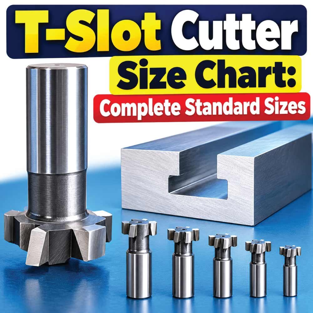
Choosing the right T-slot cutter is important when machining T-shaped slots for machine tables, fixtures, workholding systems, and other components. A cutter that is too small, too large, too thick, or incorrectly matched to the slot can produce poor fit, excessive cutting forces, or an unusable T-slot.
This T-slot cutter size chart explains common cutter dimensions, slot relationships, cutter types, shank sizes, and practical selection factors. It also explains how T-slot cutters work, how to measure an existing slot, how to select a cutter for a required T-nut, and which mistakes to avoid during machining.
Because cutter dimensions vary by manufacturer and standard, the tables below should be treated as a practical sizing reference rather than a substitute for the cutter manufacturer’s drawing.
What Is a T-Slot Cutter?
A T-slot cutter is a specialized milling cutter used to machine a T-shaped groove in a workpiece. The slot normally begins as a straight or rectangular groove and is then widened underneath the surface to create the lower portion of the T profile.
The resulting shape allows a T-nut, stud, bolt, or specialized workholding hardware to sit inside the undercut portion while the top surface remains accessible for clamping.
T-slot cutters are commonly used on:
- Milling machine tables
- CNC machine fixtures
- Workholding plates
- Machine-tool bases
- Inspection fixtures
- Modular tooling plates
- Manufacturing jigs
- Custom clamping systems
- Aluminum and steel machine components
A typical T-slot cutter has a relatively narrow cutting body compared with its overall diameter. This geometry allows the cutter to enter through an existing slot and enlarge the lower section without cutting away the entire upper opening.
T-Slot Cutter Size Chart
T-slot cutters are available in many metric and inch sizes. The exact combination of cutter diameter, thickness, neck diameter, shank diameter, and cutting height depends on the manufacturer.
The following chart illustrates commonly encountered size ranges and the relationships that matter when selecting a cutter.
| Nominal T-Slot Size | Approx. Cutter Diameter | Typical Cutter Thickness | Common Shank Range | Typical Use |
|---|---|---|---|---|
| M3–M4 | 8–12 mm | 2–3 mm | 6 mm | Small fixtures |
| M5–M6 | 12–18 mm | 3–5 mm | 6–10 mm | Light workholding |
| M8 | 18–25 mm | 4–6 mm | 10–12 mm | General fixtures |
| M10 | 22–30 mm | 5–7 mm | 10–16 mm | Medium workholding |
| M12 | 28–36 mm | 6–8 mm | 12–16 mm | Heavy fixtures |
| M14–M16 | 32–45 mm | 7–10 mm | 16–20 mm | Large workholding |
| M18–M20 | 40–55 mm | 8–12 mm | 16–25 mm | Heavy-duty applications |
These are general dimensional ranges, not universal standards. A cutter described as suitable for an M10 or M12 T-slot does not necessarily have identical dimensions across brands.
The T-slot itself must be matched to the intended T-nut or fastening hardware, not simply to the cutter’s nominal label.
Understanding T-Slot Cutter Dimensions
Reading a T-slot cutter drawing becomes much easier when each dimension is understood separately.
Cutter Diameter
The cutter diameter is the maximum outside diameter of the cutting portion. It determines how wide the lower section of the T-slot can be machined.
A larger diameter generally creates a wider undercut, but the diameter must remain compatible with the workpiece thickness and required slot geometry.
Cutter Thickness
Cutter thickness refers to the axial width of the cutting body. It is especially important because it controls the width of the lower section of the T-slot.
The thickness should correspond to the slot specification and the clearance required by the T-nut or other hardware.
Shank Diameter
The shank is the portion held by the milling machine’s collet, holder, or chuck.
Common shank diameters include:
- 6 mm
- 8 mm
- 10 mm
- 12 mm
- 16 mm
- 20 mm
- 1/4 inch
- 3/8 inch
- 1/2 inch
- 5/8 inch
- 3/4 inch
The shank must match the tool holder and provide sufficient rigidity for the operation.
Neck Diameter
The neck is the narrower section between the shank and cutting head on many T-slot cutters. Its diameter determines how much clearance the tool has inside the initial slot.
If the neck is too large, the cutter may not pass through the opening even when the cutting diameter appears suitable.
Cutting Height
Cutting height describes the vertical extent of the cutting section. It determines how deeply the cutter can form the lower portion of the T-slot in a single suitable setup.
Always compare this dimension with the required slot depth.
Metric T-Slot Cutter Sizes
Metric T-slot cutters are commonly selected according to the metric fastening system used in the fixture or machine table.
Typical applications may involve M5, M6, M8, M10, M12, M14, M16, M18, or M20 hardware.
However, the letter and number alone should not be used to select the cutter. For example, an M10 T-nut has a nominal thread size of 10 mm, but the surrounding T-slot dimensions are considerably larger.
| Hardware Thread | Important Slot Dimensions to Check | Typical Application |
|---|---|---|
| M5 | Opening, undercut width, depth | Small fixtures |
| M6 | Opening, undercut width, depth | Light-duty tables |
| M8 | Opening, undercut width, depth | General machining |
| M10 | Opening, undercut width, depth | Medium fixtures |
| M12 | Opening, undercut width, depth | Heavy workholding |
| M16 | Opening, undercut width, depth | Large machine fixtures |
| M20 | Opening, undercut width, depth | Heavy-duty systems |
The actual slot dimensions should come from the machine-table or T-nut specification whenever compatibility matters.
Inch T-Slot Cutter Sizes
Inch-based machines and fixtures commonly use fractional or numbered T-slot hardware. Cutter dimensions may therefore be specified in inches rather than millimeters.
Common nominal hardware sizes can include:
- 1/4 inch
- 5/16 inch
- 3/8 inch
- 1/2 inch
- 5/8 inch
- 3/4 inch
- 7/8 inch
- 1 inch
The thread diameter is only one part of the sizing system. The T-slot opening, neck clearance, undercut width, and slot depth must all correspond to the intended hardware.
When replacing a cutter on an existing machine table, measuring the actual slot is usually more reliable than assuming its dimensions from the thread size alone.
Standard T-Slot Cutter Types
Different T-slot cutter designs are intended for different machining requirements.
Single-Angle or Side-Cutting T-Slot Cutters
These cutters have cutting edges positioned around the outer circumference and sides of the cutting head. They are designed specifically for producing the undercut portion of a T-slot.
They are commonly used on conventional milling machines and CNC machines.
Staggered-Tooth T-Slot Cutters
Some larger cutters use staggered teeth to distribute cutting forces and improve chip clearance.
They can be useful for deeper or wider slots where efficient material removal is important.
Carbide T-Slot Cutters
Carbide cutters provide high hardness and wear resistance and are often selected for demanding machining conditions or harder workpiece materials.
They require appropriate machine rigidity because a brittle carbide cutting edge is less tolerant of severe shock or unstable setups.
High-Speed Steel T-Slot Cutters
HSS T-slot cutters are widely used for general-purpose machining. HSS offers good toughness and can be appropriate for lower-speed milling and many conventional machine-tool applications.
They are also useful where the cutter may experience interrupted cutting.
T-Slot Cutter Material Comparison
Cutter material affects tool life, cutting speed capability, toughness, and suitability for different workpieces.
| Cutter Material | General Characteristics | Typical Consideration |
|---|---|---|
| HSS | Tough and versatile | General-purpose milling |
| Cobalt HSS | Better hot hardness than standard HSS | More demanding cutting |
| Carbide | High hardness and wear resistance | Higher-performance machining |
| Coated Carbide | Improved wear and heat resistance depending on coating | Production machining |
The workpiece material, machine rigidity, coolant strategy, cutting parameters, and tool geometry all affect actual performance.
How T-Slot Cutters Work
A T-slot is normally produced in two machining stages.
Step 1: Machine the Initial Slot
A standard end mill or slotting cutter creates the narrow upper opening.
The opening must be large enough to allow the neck of the T-slot cutter to pass through.
Step 2: Machine the Undercut
The T-slot cutter is lowered through the existing opening and moved laterally to remove material underneath the surface.
This creates the wider lower section.
The finished profile resembles the letter T, which gives the slot its name.
The machining sequence is important because attempting to create the complete profile directly with a T-slot cutter is generally not the intended method.
How to Measure an Existing T-Slot
When selecting a replacement cutter or T-nut, measure the existing slot carefully.
Measure the Top Opening
Measure the visible width at the top of the slot.
This determines the maximum neck or cutting-body dimensions that can pass through the opening.
Measure the Undercut Width
The lower section is usually wider than the top opening. Measure the maximum width across the internal undercut.
This is one of the most important dimensions for identifying compatible T-slot hardware.
Measure the Slot Depth
Measure from the workpiece surface to the bottom of the slot.
For an existing machine table, avoid assuming the depth based only on the nominal T-slot size.
Measure the T-Nut
If a T-nut is already available, measure:
- Thread size
- Overall width
- Overall height
- Flange or shoulder dimensions
- Slot engagement dimensions
The T-nut dimensions can provide valuable information when identifying the required slot profile.
Also Read:
How to Choose the Correct T-Slot Cutter
Selecting a cutter involves more than matching the cutter diameter to a catalog number.
Match the Required T-Slot Profile
Start with the actual required slot dimensions.
Identify:
- Top opening width
- Undercut width
- Undercut depth
- Overall slot depth
- Corner or clearance requirements
The cutter must be capable of producing the required profile without interfering with the upper opening.
Check Cutter Diameter
The cutter diameter needs to be large enough to machine the intended undercut while remaining suitable for the available material thickness.
A cutter that is unnecessarily large can increase cutting forces.
Check Cutter Thickness
The cutter thickness should correspond to the width of the lower T-slot section.
A mismatch can prevent the T-nut from fitting correctly.
Check Neck Clearance
The neck must fit through the existing slot opening.
This is especially important when modifying an existing machine table because the undercut cutter must physically pass through the narrow upper opening.
Check Shank Compatibility
Make sure the shank fits your:
- Collet
- End mill holder
- Toolholder
- Milling chuck
- CNC spindle system
A suitable cutting head is not useful if the shank cannot be held securely.
T-Slot Cutter Selection by Workpiece Material
The material being machined affects tool selection and cutting conditions.
Aluminum
Aluminum can generally be machined efficiently with sharp tools designed for non-ferrous materials. Proper chip evacuation is particularly important because aluminum chips can adhere to poorly suited cutting edges.
Mild Steel
HSS and carbide cutters can both be used depending on the machine, cutter geometry, and production requirements.
Rigid workholding and appropriate cutting parameters are important because the T-slot operation involves side loading.
Stainless Steel
Stainless steel can generate substantial heat and work hardening when machining conditions are poor. A suitable cutter, controlled feed, adequate rigidity, and appropriate cooling strategy are important.
Cast Iron
Cast iron produces abrasive chips and may require cutter geometry and material suited to the grade being machined.
The manufacturer’s recommended cutting parameters should take priority over generic values.
Also Read:
T-Slot Cutter vs End Mill
A standard end mill and a T-slot cutter perform different functions.
| Feature | End Mill | T-Slot Cutter |
|---|---|---|
| Primary Function | Slots, pockets, profiles | T-shaped undercuts |
| Cutting Geometry | Usually primarily end and peripheral cutting | Narrow body with wider cutting head |
| Typical Use | Initial slot and general milling | Lower T-slot section |
| Can Create Undercut? | Limited by geometry | Yes |
| Typical Operation | Plunging/interpolation/side milling | Lateral undercutting |
An end mill is often used first to produce the opening, while the T-slot cutter creates the wider lower section.
Common T-Slot Cutter Applications
T-slot cutters are useful wherever a removable clamping or fastening system needs to be built into a machined surface.
Common applications include:
- Milling machine tables
- CNC fixture plates
- Drill press fixtures
- Welding fixtures
- Inspection fixtures
- Modular workholding plates
- Machine bases
- Custom tooling
- Assembly fixtures
- Adjustable clamping systems
The main advantage of a T-slot is that fasteners can be positioned along the slot instead of being permanently fixed at one location.
Advantages and Limitations of T-Slot Cutters
Advantages
T-slot cutters provide several practical benefits:
- They create dedicated undercut profiles for T-nuts.
- They allow adjustable workholding positions.
- They can machine compact T-slots.
- They are available in metric and inch configurations.
- Different materials and coatings support different machining conditions.
- They can be used on conventional and CNC milling machines.
Limitations
There are also limitations to consider:
- The cutter requires an existing opening for access.
- Side cutting can generate significant lateral forces.
- Small cutters can be relatively delicate.
- Incorrect slot dimensions can make the finished profile unusable.
- Deep slots can create chip-clearance challenges.
- Poorly supported workpieces can vibrate during cutting.
These limitations make setup rigidity and dimensional planning particularly important.
Also Read:
Common T-Slot Cutter Mistakes
Many T-slot machining problems result from selecting the cutter based on only one dimension.
Using Thread Size as the Cutter Size
An M10 T-nut does not mean the cutter should have a 10 mm cutting diameter.
The thread size identifies the fastener thread, while the T-slot has its own dimensional requirements.
Ignoring the Top Opening
A cutter may have the correct undercut diameter but still fail to enter the slot because its neck or cutting section is too large.
Always check clearance through the opening.
Cutting the Undercut Too Deep
Excessive depth can weaken the remaining material beneath the work surface or create a slot that does not match the intended hardware.
Using an Incompatible T-Nut
Even a correctly machined T-slot can be unsuitable if the T-nut dimensions do not match.
The slot and hardware should be treated as one system.
Using Excessive Cutting Force
Aggressive feeds or unsuitable cutting parameters can cause vibration, deflection, poor surface finish, or cutter damage.
Use stable workholding and follow the cutter manufacturer’s recommendations.
Tips for Accurate T-Slot Milling
For reliable results, plan the entire operation before making the undercut.
- Verify the required T-slot drawing or dimensions.
- Machine the upper slot accurately first.
- Confirm the cutter can pass through the opening.
- Check the cutter diameter and thickness.
- Use a rigid tool holder.
- Secure the workpiece firmly.
- Avoid excessive tool overhang.
- Ensure chips can evacuate from the slot.
- Take controlled cuts appropriate for the machine and material.
- Inspect the finished slot before installing the T-nut.
- Test-fit the actual hardware whenever practical.
For CNC machining, the toolpath should also account for the cutter’s actual geometry rather than treating it like a conventional end mill.
How Deep Should a T-Slot Be?
There is no single universal T-slot depth because the required depth depends on the T-slot standard, machine design, T-nut dimensions, material thickness, and application.
The lower portion must provide enough clearance for the intended fastening hardware while maintaining sufficient material around the slot.
When designing a custom T-slot, consider:
- Required thread size
- T-nut dimensions
- Slot opening
- Undercut width
- Undercut height
- Available material thickness
- Required clamping strength
- Edge distance
- Fastener clearance
For an existing machine table, use the manufacturer’s slot drawing when available.
T-Slot Cutter Size Chart: What to Check Before Buying
Before ordering a cutter, create a simple dimensional checklist.
| Dimension | Why It Matters |
|---|---|
| Cutter diameter | Controls undercut width |
| Cutter thickness | Controls lower slot width |
| Shank diameter | Must fit the tool holder |
| Neck diameter | Must pass through the slot opening |
| Cutting height | Determines usable undercut depth |
| Overall length | Affects reach and clearance |
| Number of teeth | Influences chip load and cutting behavior |
| Material | Determines tool characteristics |
| Coating | Can affect wear and cutting performance |
Checking all of these dimensions is much safer than selecting a cutter solely from a nominal T-slot label.
Frequently Asked Questions
What size cutter is used for a T-slot?
The correct cutter depends on the required T-slot profile. Cutter diameter, thickness, neck diameter, and cutting height must correspond to the slot dimensions and intended T-nut.
Can a T-slot cutter make the entire slot?
A T-slot cutter is normally used to machine the lower undercut after a suitable upper opening has already been created. A conventional end mill is commonly used for the initial slot.
How do I know what T-slot cutter I need?
Start with the T-slot drawing or measure the existing slot. Check the opening width, undercut width, depth, cutter thickness, cutter diameter, neck clearance, and shank compatibility.
Are metric and inch T-slot cutters interchangeable?
Not necessarily. Metric and inch systems can have different slot and fastening dimensions. Even when dimensions appear close, the T-nut and slot may not fit correctly.
What is the difference between a T-slot cutter and a Woodruff cutter?
Both cutters have specialized profiles, but they are intended for different machining operations. A T-slot cutter is designed to create the undercut of a T-shaped groove, while a Woodruff cutter is primarily associated with keyseat machining.
Can carbide be used for T-slot milling?
Yes. Carbide T-slot cutters are available and can provide high wear resistance, but the machine and setup should be sufficiently rigid. Cutter geometry and manufacturer’s recommended parameters remain important.
Why does my T-slot cutter chatter?
Chatter can result from excessive tool overhang, insufficient workholding, inappropriate cutting parameters, a weak machine setup, or an unsuitable cutter. Reducing unsupported tool length and improving rigidity are common starting points for troubleshooting.
Should the T-slot be measured before buying a cutter?
Yes, particularly when repairing or modifying an existing machine table. Measuring the actual slot reduces the risk of purchasing a cutter that cannot produce the required profile.
Final Takeaway
A T-slot cutter size chart is useful for narrowing down cutter options, but the nominal T-slot or thread size should never be the only selection criterion. The actual cutter diameter, thickness, neck diameter, shank, cutting height, and slot geometry all need to work together.
For new T-slot designs, begin with the required T-nut or fastening system and work backward to the slot dimensions. For existing slots, measure the opening, undercut, depth, and hardware before choosing a replacement tool.
The most reliable approach is to compare the required dimensions with the manufacturer’s cutter drawing and the applicable machine or T-slot specification. This helps ensure the finished slot provides the required fit, clearance, and workholding performance.

Engineer Hassan is a Mechanical Engineer with 16+ years of hands-on experience in mechanical hardware, fasteners, and workshop tools. He focuses on size selection, thread identification, and measurement, helping users choose the correct components with accuracy and safety.