
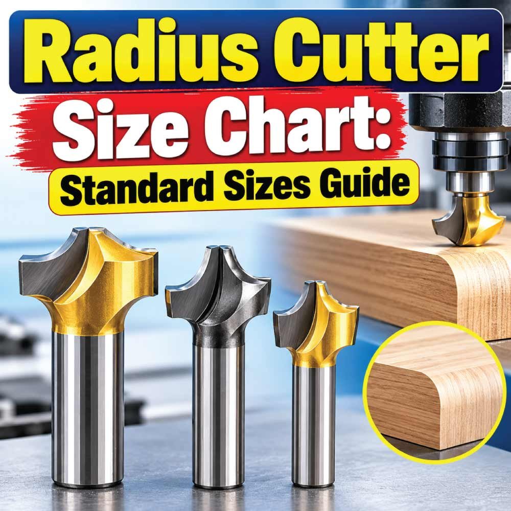
A radius cutter size chart helps machinists identify the correct cutter radius, cutting diameter, shank size, and overall dimensions for a particular machining job. Choosing the right radius is important when producing rounded edges, grooves, profiles, and other curved features accurately.
Radius cutters are available in different designs, including concave radius cutters, convex radius cutters, corner-rounding cutters, and specialized form tools. Their dimensions can vary significantly according to cutter style, manufacturer, tooling system, and whether the tool is intended for a manual mill, CNC machining center, or another machine.
This guide explains radius cutter sizes, important dimensions, cutter types, measurement methods, applications, selection factors, and common mistakes. Because manufacturers do not use one universal dimensional system for every radius cutter, always compare the nominal cutting radius and complete tool dimensions with the cutter manufacturer’s specifications before machining.
What Is a Radius Cutter?
A radius cutter is a milling tool designed to produce a controlled curved or rounded profile on a workpiece. Instead of creating a sharp corner or straight-sided feature, the cutter removes material according to its specified radius.
The term can describe several different milling tools. A cutter may create a concave radius, a convex radius, or a rounded edge depending on its geometry.
The most important specification is usually the cutting radius. This determines the curvature produced by the cutting edge.
Other dimensions can include:
- Cutting diameter
- Radius
- Cutter width
- Overall cutter diameter
- Shank diameter
- Cutting length
- Neck diameter
- Overall tool length
- Number of flutes
- Bore diameter for arbor-mounted cutters
The exact dimensions that matter depend on the cutter design and the machining operation.
Radius Cutter Size Chart
The following chart organizes the main dimensions that should be considered when selecting a radius cutter. It is intentionally presented as a specification guide rather than a fabricated universal manufacturer’s size table because actual cutter dimensions vary between tooling designs and brands.
| Cutter Specification | What It Means | Why It Matters |
|---|---|---|
| Radius (R) | Nominal curve radius produced by the tool | Determines the finished profile |
| Cutting Diameter | Diameter associated with the cutting profile | Affects tool path and clearance |
| Shank Diameter | Diameter of the tool-holding portion | Must match the holder or collet |
| Cutting Length | Axial length of the active cutting area | Determines usable cutting depth |
| Overall Length | Total tool length | Affects reach and machine clearance |
| Cutter Width | Width of the cutting body or form | Important for profile and side clearance |
| Bore Diameter | Internal hole on arbor-mounted cutters | Must match the arbor |
| Flute Count | Number of cutting edges/flutes | Influences chip evacuation and cutting behavior |
The radius should be selected from the required workpiece profile, while the remaining dimensions must be checked against the machine, holder, workpiece geometry, and available clearance.
Understanding Radius Cutter Dimensions
Not every dimension shown on a catalog drawing describes the radius itself. Understanding the terminology makes it easier to compare cutters correctly.
Cutting Radius
The cutting radius is the distance from the center of the intended circular profile to the cutting surface. It is normally identified as R on technical drawings.
For example, a specification marked R5 indicates a nominal 5 mm radius. The corresponding full diameter of that circular geometry would be 10 mm if the feature represents a complete diameter relationship.
The cutter must be selected according to the radius required on the workpiece rather than simply according to the cutter’s outside diameter.
Cutting Diameter
Cutting diameter describes the diameter across the relevant cutting profile. Depending on cutter geometry, this may not be the same as the finished feature diameter.
For a simple circular relationship:
Diameter = 2 × Radius
Therefore:
| Radius | Equivalent Diameter |
|---|---|
| 1 mm | 2 mm |
| 2 mm | 4 mm |
| 3 mm | 6 mm |
| 4 mm | 8 mm |
| 5 mm | 10 mm |
| 6 mm | 12 mm |
| 10 mm | 20 mm |
These are mathematical radius-to-diameter relationships, not claims about available commercial cutter sizes.
Shank Diameter
The shank is the portion held by a collet, tool holder, chuck, or other clamping system.
A cutter with the correct radius can still be unsuitable if its shank does not match the available holder.
Before ordering or installing a cutter, check:
- Holder type
- Collet capacity
- Shank diameter
- Maximum tool diameter
- Machine spindle compatibility
- Required tool reach
Overall Length
Overall tool length affects how far the cutter extends from the holder. Longer tools can provide greater reach but may also introduce additional deflection and vibration.
The shortest tool that safely reaches the required machining area is often preferable for rigidity.
Common Radius Cutter Types
Different cutter geometries are designed for different profile requirements. Understanding the distinction is essential because a radius specification alone does not completely describe a tool.
Concave Radius Cutter
A concave radius cutter produces an inward-curving profile. The cutting edge contains a concave form that removes material to create a rounded groove or internal contour.
Typical applications include:
- Rounded grooves
- Formed channels
- Internal curved profiles
- Decorative machining
- Mold and die features
The workpiece profile should be checked carefully because the cutter’s orientation and geometry determine how the concave form is produced.
Convex Radius Cutter
A convex radius cutter creates an outward-curving profile. It can be used when a rounded projection or external curved surface is required.
Applications may include:
- External rounded profiles
- Form machining
- Edge treatments
- Decorative components
- Specialized mechanical parts
Corner-Rounding Cutter
A corner-rounding cutter is commonly used to place a radius on the edge of a workpiece. Rather than machining a complete curved groove, it rounds an otherwise sharp corner.
This makes it useful for:
- Removing sharp edges
- Producing controlled edge radii
- Preparing components for assembly
- Creating repeatable external corner profiles
Radius End Mill
Some end mills incorporate a rounded or corner-radius geometry into their cutting profile. These tools may be used for general milling, contouring, pocketing, and finishing where a controlled corner radius is required.
The term corner radius end mill is particularly important in CNC machining because the radius is part of the tool’s cutting geometry rather than necessarily being the entire cutting profile.
Metric Radius Cutter Sizes
Metric tooling identifies the radius primarily in millimeters. The exact commercially available sizes depend on the cutter design and manufacturer.
A useful reference for understanding metric radius selection is:
| Nominal Radius | Equivalent Diameter Relationship | Typical Selection Consideration |
|---|---|---|
| R1 mm | 2 mm | Small-radius features |
| R2 mm | 4 mm | Small rounded profiles |
| R3 mm | 6 mm | General profile work |
| R4 mm | 8 mm | Medium-radius features |
| R5 mm | 10 mm | Common larger edge radius |
| R6 mm | 12 mm | Larger rounded profiles |
| R8 mm | 16 mm | Large profile applications |
| R10 mm | 20 mm | Large-radius machining |
This table illustrates the mathematical relationship between radius and diameter. It should not be treated as a universal catalog of available cutters.
When purchasing metric tooling, confirm the manufacturer’s actual radius, cutting diameter, shank diameter, flute length, and overall length.
Inch Radius Cutter Sizes
Inch-based tooling uses fractional or decimal-inch measurements. The same geometric relationship applies:
R = D ÷ 2
and
D = 2R
Common inch radius notation may appear in drawings or tooling documentation as values such as R1/8, R1/4, R3/8, or R1/2, depending on the application and tool design.
| Nominal Radius | Equivalent Diameter |
|---|---|
| 1/16 in | 1/8 in |
| 1/8 in | 1/4 in |
| 3/16 in | 3/8 in |
| 1/4 in | 1/2 in |
| 3/8 in | 3/4 in |
| 1/2 in | 1 in |
These values are geometric conversions rather than a statement that every radius cutter is manufactured in each listed size.
When working from an imperial engineering drawing, do not substitute a nearby metric cutter simply because the nominal dimensions appear similar. The resulting profile may differ enough to affect fit, appearance, or function.
How to Measure a Radius Cutter
Correct measurement starts with identifying what dimension needs to be verified. Measuring the outside of a cutter does not necessarily reveal its cutting radius.
Step 1: Identify the Cutter Geometry
First determine whether the tool is:
- Concave
- Convex
- Corner-rounding
- Radius end mill
- Form cutter
- Another specialized profile cutter
The measurement method depends on the geometry.
Step 2: Check the Markings
Many cutting tools have identifying information on the shank, packaging, or manufacturer’s documentation.
Look for:
- Radius designation
- Cutter diameter
- Shank diameter
- Tool number
- Metric or imperial designation
- Coating or material designation
The manufacturer’s drawing is generally more reliable than estimating the radius from the physical appearance of a small cutter.
Step 3: Measure the Shank
Use an appropriate precision measuring instrument, such as a micrometer or caliper, to check the shank diameter.
Take measurements on a clean, undamaged section of the shank. Do not measure across burrs or contamination.
Step 4: Verify the Cutting Profile
For the radius itself, use the cutter’s technical drawing or an appropriate radius gauge where practical.
For precision applications, optical inspection or specialized metrology may be more appropriate than attempting to measure a small radius with a standard caliper.
Also Read:
How to Choose the Correct Radius Cutter
Choosing a cutter begins with the required finished radius, but several additional factors determine whether the tool will work properly.
Match the Required Radius
Start with the engineering drawing, CAD model, or finished-part requirement.
If the drawing calls for a specific radius, select a cutter designed to produce that geometry rather than choosing a tool based only on approximate diameter.
Check Material Compatibility
Workpiece material influences cutter selection.
Consider whether you are machining:
- Aluminum
- Mild steel
- Stainless steel
- Tool steel
- Cast iron
- Brass
- Copper
- Engineering plastics
- Composite materials
Tool material, coating, flute geometry, cutting parameters, and coolant strategy may need to change according to the workpiece.
Check Machine Compatibility
Make sure the cutter is suitable for the machine’s spindle and tool-holding system.
Check:
- Maximum spindle speed
- Holder capacity
- Shank diameter
- Available horsepower
- Machine rigidity
- Tool reach
- Workholding arrangement
Consider Clearance
The cutter needs sufficient clearance around the workpiece and holder.
A radius cutter that fits the feature but interferes with an adjacent wall, clamp, fixture, or machine component is not suitable for the operation.
Radius Cutter Selection Chart
The following chart provides a practical way to organize the selection process.
| Requirement | What to Check | Selection Priority |
|---|---|---|
| Finished radius | Drawing or CAD dimension | Highest |
| Cutter geometry | Concave, convex, corner radius, or form | Highest |
| Workpiece material | Hardness and machinability | High |
| Tool holder | Shank and clamping compatibility | High |
| Cutting depth | Required flute engagement | High |
| Machine clearance | Tool and holder envelope | High |
| Tool reach | Distance to feature | Medium |
| Flute configuration | Cutting and chip evacuation requirements | Medium |
| Coating | Compatibility with material and operation | Medium |
| Coolant method | Dry, flood, mist, or through-tool as applicable | Medium |
This approach prevents the common mistake of selecting a cutter solely because its advertised radius appears correct.
Also Read:
Applications of Radius Cutters
Radius cutters are used whenever a controlled curved profile is required.
Common applications include:
- Edge rounding on machined components
- Groove production where a curved internal profile is needed
- Form milling for repeatable profiles
- Mold and die machining
- Prototype manufacturing
- CNC contouring
- Mechanical component production
- Decorative machining
- Fixture and tooling manufacture
- General workshop milling
The appropriate cutter depends on whether the desired radius is external, internal, edge-based, or part of a larger three-dimensional contour.
Radius Cutter vs Corner Radius End Mill
These terms are sometimes used interchangeably, but they can describe different tool geometries.
A dedicated radius or form cutter may be designed specifically to produce a particular curved profile. A corner radius end mill, by contrast, has a rounded transition between its end cutting edge and peripheral cutting edge.
The distinction matters because the resulting tool path and finished geometry are different.
| Feature | Radius/Form Cutter | Corner Radius End Mill |
|---|---|---|
| Primary purpose | Producing a defined curved form | Milling with a rounded tool corner |
| Profile control | Often centered around the form radius | Radius is part of end-mill geometry |
| Typical use | Specialized profiling | General CNC milling and contouring |
| Tool path | Depends strongly on cutter form | Commonly used in programmed milling paths |
| Selection basis | Required profile and cutter geometry | Radius, diameter, flute length, and application |
Always identify the intended finished geometry before choosing between the two.
Also Read:
Advantages of Using the Correct Radius Cutter
Using a properly selected cutter can provide several practical benefits.
Consistent Profiles
A dedicated radius tool can produce a repeatable profile when the cutter geometry matches the required feature.
Reduced Manual Finishing
A correctly selected cutter can eliminate or reduce the need for extensive manual rounding or blending.
Improved Part Consistency
In production environments, repeatable tooling geometry can help maintain consistent dimensions between parts.
Better Edge Quality
The appropriate radius can reduce unnecessarily sharp edges and produce a controlled transition between surfaces.
Simplified CNC Programming
When the cutter geometry is clearly defined, it can be incorporated into a predictable machining strategy.
Common Radius Cutter Problems
Even a correctly sized cutter can produce poor results if the machining setup is unsuitable.
Wrong Radius
A cutter may be installed with the wrong nominal radius, resulting in a profile that does not match the drawing.
Excessive Tool Deflection
Long tool projection increases the risk of deflection, especially during heavy cutting.
Symptoms may include:
- Dimensional variation
- Chatter
- Poor surface finish
- Uneven radius
- Increased tool wear
Insufficient Clearance
The cutter body or holder can collide with the workpiece or fixture if clearance is not checked before machining.
Incorrect Tool Orientation
Form cutters are sensitive to orientation. Installing the tool incorrectly can produce the wrong profile or interfere with surrounding surfaces.
Poor Workholding
Movement of the workpiece can make an accurately manufactured cutter appear to produce an inaccurate radius.
Tips for Accurate Radius Machining
A few practical checks can improve machining consistency.
- Verify the radius before machining.
- Confirm whether the drawing uses metric or imperial dimensions.
- Keep tool projection as short as practical.
- Use a rigid tool-holding setup.
- Check cutter orientation carefully.
- Verify machine and fixture clearance.
- Use appropriate feeds and speeds for the material and cutter.
- Inspect the first machined feature before running a large batch.
- Account for tool wear in production work.
- Use the manufacturer’s dimensional drawing when exact cutter geometry matters.
For CNC machining, also verify that the programmed tool path accounts for the actual cutter geometry rather than assuming that the cutter diameter alone defines the finished feature.
Frequently Asked Questions
What does R mean on a radius cutter?
R normally identifies the nominal radius of the cutting profile. For example, R5 represents a 5 mm radius. The exact meaning should still be confirmed against the particular cutter drawing.
Is a radius cutter the same as a ball nose end mill?
No. A ball nose end mill has a hemispherical or ball-shaped cutting end and is commonly used for three-dimensional contouring. A dedicated radius cutter may have a different profile intended to produce a specific rounded feature.
How do I calculate cutter diameter from radius?
Use:
D = 2R
For example, a 4 mm radius corresponds to a 8 mm diameter in the simple circular relationship.
Can one radius cutter make different radii?
A fixed-profile radius cutter is generally intended for its specified geometry. Variable or programmable machining strategies can produce different radii, but a dedicated fixed-radius cutter should not be assumed to produce arbitrary profiles.
What is the most important radius cutter dimension?
For profile selection, the required cutting radius is usually the first dimension to identify. However, shank diameter, cutting length, overall length, clearance, and cutter geometry are also essential.
Should I choose the cutter by diameter or radius?
Choose it primarily according to the required finished profile and radius, then verify the cutter diameter and other dimensions for machine compatibility and clearance.
Can radius cutters be used on CNC machines?
Yes. Many radius and form cutters are suitable for CNC milling. The specific tool must be compatible with the machine, holder, material, spindle conditions, and programmed tool path.
Why does my machined radius not match the cutter specification?
Possible causes include incorrect cutter geometry, tool wear, deflection, incorrect tool offset, improper tool orientation, machine movement, measurement error, or an incorrect machining path.
Final Takeaway
A radius cutter size chart is most useful when it is treated as a starting point for identifying the required radius and associated tool dimensions rather than as a universal catalog. Radius cutters differ by geometry, mounting method, cutting diameter, shank size, length, and intended application.
Start with the finished radius shown on the drawing, identify the correct cutter type, and then verify shank compatibility, cutting depth, clearance, workpiece material, and machine limitations. For exact production work, use the cutter manufacturer’s dimensional drawing and recommended machining information.
Selecting the cutter by the complete geometry—not simply by a radius number—helps produce the intended profile while reducing clearance problems, dimensional errors, and unnecessary tool changes.

Engineer Hassan is a Mechanical Engineer with 16+ years of hands-on experience in mechanical hardware, fasteners, and workshop tools. He focuses on size selection, thread identification, and measurement, helping users choose the correct components with accuracy and safety.