
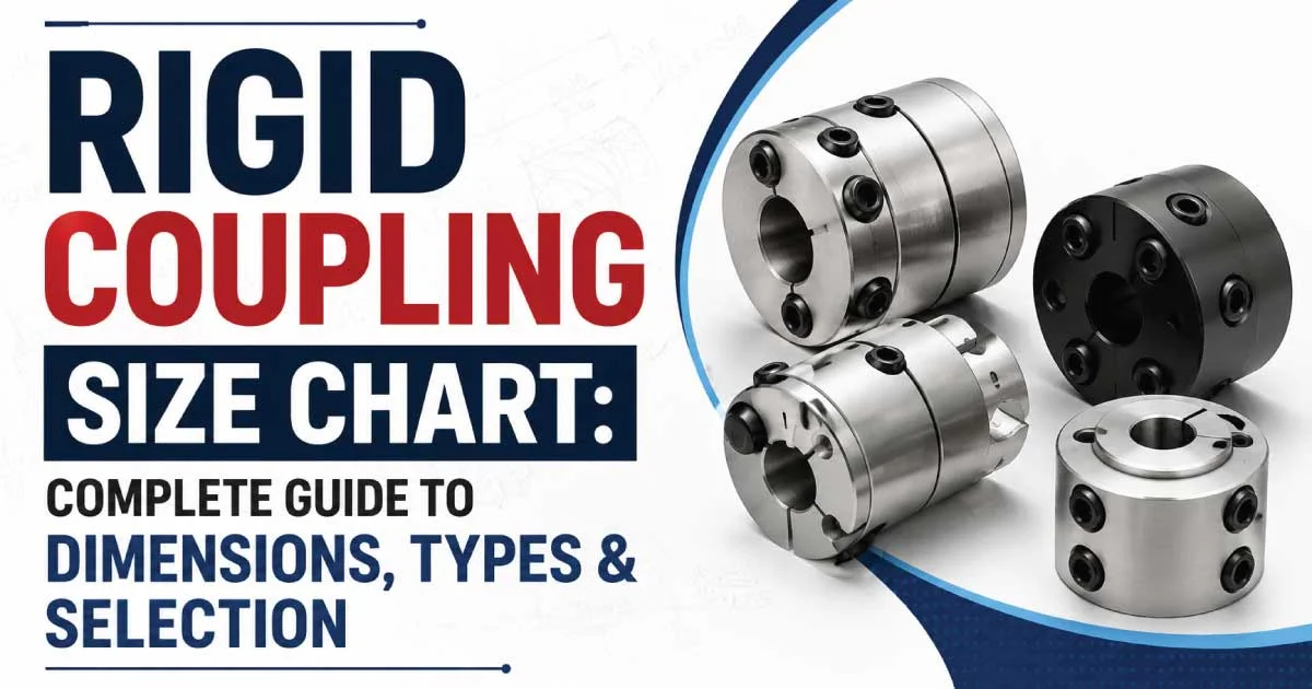
A rigid coupling size chart is an essential reference for engineers, technicians, and maintenance professionals who need to connect two shafts with maximum accuracy.
It provides dimensions, bore sizes, outside diameters, and torque capacities, making the selection process easier.
Using the correct chart minimizes installation errors, improves performance, and extends equipment life in industrial applications.
What Is a Rigid Coupling?
A rigid coupling is a mechanical component designed to permanently connect two shafts so they rotate as a single unit without allowing angular, parallel, or axial misalignment. These couplings provide excellent torque transmission and are commonly used in machines where shaft alignment is highly accurate and movement between shafts is not expected.
Key Features of Rigid Couplings
- High torque transmission capability
- Zero backlash during operation
- Simple and durable construction
- Minimal maintenance requirements
- Excellent shaft alignment performance
- Cost-effective for fixed installations
Why a Rigid Coupling Size Chart Matters
Selecting a coupling without consulting a size chart can lead to premature equipment failure, vibration, and reduced efficiency. A rigid coupling size chart helps users identify the correct bore diameter, shaft size, keyway dimensions, and overall coupling dimensions, ensuring compatibility between connected components and improving overall system reliability.
How to Read a Rigid Coupling Size Chart
Understanding a rigid coupling size chart is straightforward once you know what each column represents. Most charts include shaft diameter, outside diameter, coupling length, keyway dimensions, bolt size, and maximum torque rating. Comparing these specifications with your machinery requirements ensures the best coupling selection for safe and efficient operation.
Common Information Included in Size Charts
- Coupling model number
- Shaft bore diameter
- Outside diameter (OD)
- Coupling length
- Keyway dimensions
- Bolt specifications
- Maximum torque capacity
- Material type
- Weight
Standard Components of a Rigid Coupling
Rigid couplings consist of several important components that work together to create a secure shaft connection. Although designs vary slightly between manufacturers, the basic construction remains nearly identical, providing strength, stability, and reliable torque transmission in industrial environments.
Main Components
- Hub
- Bore
- Keyway
- Set screws or clamping bolts
- Flange (for flange-type couplings)
- Fasteners
- Shaft interface
Types of Rigid Couplings
Rigid couplings are available in different configurations depending on installation requirements. Each type offers unique advantages while maintaining the same fundamental purpose of creating a solid shaft connection. Choosing the right style depends on shaft accessibility, maintenance needs, and operating conditions.
Sleeve Coupling
Sleeve couplings are the simplest type, consisting of a hollow cylindrical sleeve that fits over both shaft ends. They are economical, compact, and suitable for light to medium-duty applications where shaft disassembly is infrequent.
Split Muff Coupling
Split muff couplings consist of two halves bolted together around the shafts. They simplify installation and removal without disturbing adjacent machine components, making them popular for maintenance-friendly industrial systems.
Flange Coupling
Flange couplings feature two flanged hubs connected with bolts. They provide exceptional torque transmission and are widely used in pumps, compressors, turbines, and heavy industrial machinery requiring reliable shaft alignment.
Clamp Coupling
Clamp couplings secure shafts using clamping pressure instead of set screws. This design minimizes shaft damage while providing a firm grip, making them suitable for precision equipment and applications requiring frequent adjustments.
Common Materials Used in Rigid Couplings
Material selection directly affects coupling strength, corrosion resistance, durability, and operating life. Manufacturers produce rigid couplings using several materials to suit varying industrial environments and performance requirements.
Popular Materials
- Cast iron
- Carbon steel
- Stainless steel
- Alloy steel
- Aluminum
- Brass (special applications)
Each material offers different advantages regarding corrosion resistance, strength, weight, and operating temperature.
Typical Rigid Coupling Size Chart
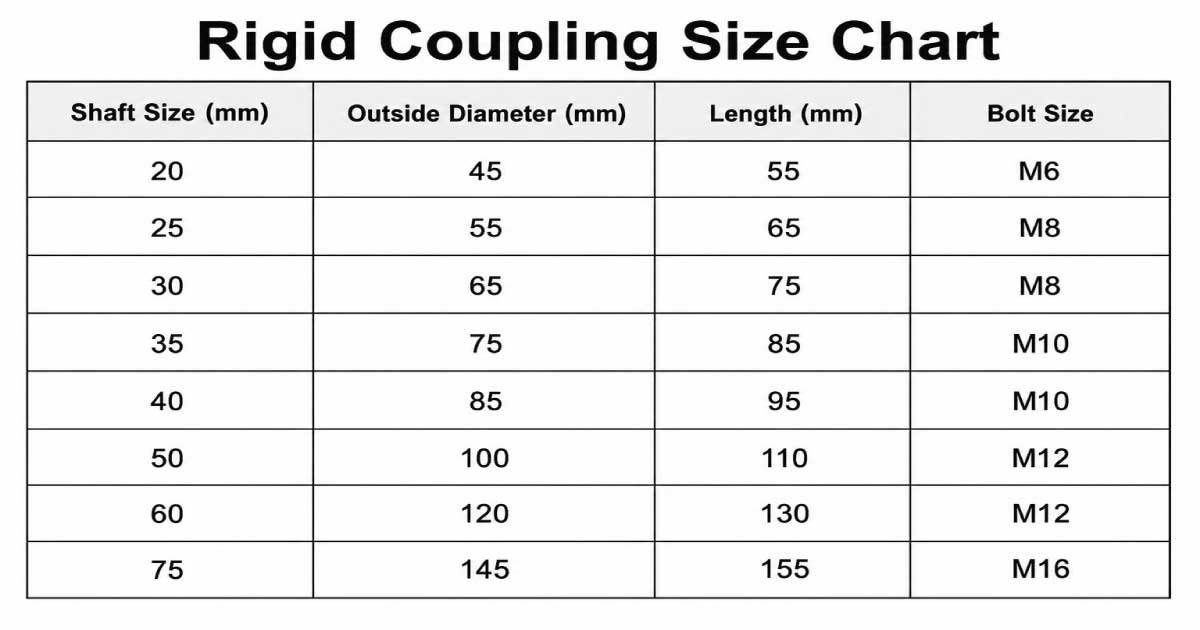
The following example illustrates common coupling dimensions. Actual specifications vary by manufacturer, but this chart provides a general reference.
| Shaft Size (mm) | Outside Diameter (mm) | Length (mm) | Bolt Size |
|---|---|---|---|
| 20 | 45 | 55 | M6 |
| 25 | 55 | 65 | M8 |
| 30 | 65 | 75 | M8 |
| 35 | 75 | 85 | M10 |
| 40 | 85 | 95 | M10 |
| 50 | 100 | 110 | M12 |
| 60 | 120 | 130 | M12 |
| 75 | 145 | 155 | M16 |
Rigid Coupling Size Chart PDF
A rigid coupling size chart helps you select the correct coupling based on shaft diameter, outside diameter, length, and bolt size. Choosing the proper size ensures accurate shaft alignment, reliable torque transmission, and long-lasting performance. Use this chart as a quick reference for selecting rigid couplings in industrial and mechanical applications.
Always verify dimensions using the manufacturer’s official size chart before purchasing or installing a coupling.
Factors to Consider When Selecting the Correct Size
Choosing the right rigid coupling involves more than matching shaft diameter. Operating conditions, torque, environmental factors, and installation requirements all influence the correct selection. Evaluating these factors carefully helps prevent unexpected downtime and mechanical failures.
Selection Checklist
- Shaft diameter
- Torque requirement
- Rotational speed
- Operating temperature
- Material compatibility
- Installation space
- Maintenance accessibility
- Industry standards
- Environmental conditions
Advantages of Using Properly Sized Rigid Couplings
Properly sized rigid couplings improve machinery performance by maintaining accurate shaft alignment and reducing unnecessary stress. They also increase operational efficiency, decrease maintenance costs, and provide dependable power transmission for demanding industrial applications.
Major Benefits
- Improved equipment reliability
- Reduced vibration
- Increased torque efficiency
- Longer machinery lifespan
- Lower maintenance costs
- Easy installation
- Stable shaft alignment
Industries That Commonly Use Rigid Couplings
Rigid couplings are found across numerous industries where precise shaft alignment is essential. Their robust construction makes them suitable for continuous-duty operations and heavy mechanical loads in both manufacturing and processing environments.
Common Applications
- Manufacturing plants
- Mining operations
- Power generation
- Oil and gas facilities
- Chemical processing
- Water treatment plants
- Agricultural machinery
- Food processing equipment
- Conveyor systems
- Industrial pumps
How to Measure a Rigid Coupling Correctly
Accurate measurement is the foundation of selecting the correct rigid coupling. Even minor errors in shaft or bore measurements can lead to poor alignment, excessive vibration, and premature component wear. Always use calibrated measuring tools and verify dimensions before purchasing or installing a coupling.
Tools Required for Measurement
- Vernier caliper
- Outside micrometer
- Steel ruler
- Tape measure
- Dial indicator
- Bore gauge
- Shaft alignment tool
Also Read:
Understanding Bore Size and Shaft Diameter
The bore size of a rigid coupling must precisely match the shaft diameter to achieve a secure connection. A bore that is too large causes slipping, while one that is too small prevents installation. Proper sizing ensures maximum torque transmission and minimizes mechanical stress during operation.
Importance of Torque Ratings
Torque rating indicates the maximum rotational force a coupling can safely transmit. Selecting a coupling with an insufficient torque rating can result in deformation, failure, or costly equipment damage. Always choose a coupling that exceeds the maximum operating torque while considering possible overload conditions.
Factors Affecting Torque Capacity
- Coupling material
- Bore diameter
- Shaft size
- Bolt strength
- Operating speed
- Shock loading
- Temperature
- Installation quality
Common Installation Mistakes to Avoid
Even the highest-quality rigid coupling can fail if installed incorrectly. Installation errors often lead to shaft damage, bearing wear, excessive vibration, and reduced machine efficiency. Following recommended installation procedures significantly improves coupling performance and extends equipment service life.
Frequent Installation Errors
- Incorrect shaft alignment
- Loose bolts
- Improper key installation
- Uneven bolt tightening
- Using damaged shafts
- Ignoring torque specifications
- Reusing worn fasteners
Also Read:
Step-by-Step Installation Process
Installing a rigid coupling requires careful preparation and attention to detail. Following a systematic procedure ensures proper shaft alignment, secure fastening, and reliable operation while minimizing the risk of future maintenance problems.
Installation Steps
- Clean both shaft ends thoroughly.
- Measure and verify shaft dimensions.
- Inspect the key and keyway.
- Position the coupling on the shafts.
- Align both shafts accurately.
- Install keys if required.
- Tighten bolts evenly using the recommended torque.
- Rotate the assembly manually.
- Perform a final alignment inspection.
- Test the equipment under normal operating conditions.
Maintenance Tips for Longer Service Life
Rigid couplings require relatively little maintenance, but regular inspections help prevent unexpected failures. Routine checks identify loose fasteners, corrosion, shaft wear, and alignment issues before they become major problems, improving equipment reliability and reducing downtime.
Routine Maintenance Checklist
- Inspect bolts regularly
- Check shaft alignment
- Look for corrosion
- Examine keyways
- Monitor vibration
- Clean accumulated debris
- Replace worn components
- Record inspection results
Also Read:
Signs That a Rigid Coupling Needs Replacement
Although rigid couplings are highly durable, they eventually wear out due to heavy loads, improper installation, or harsh operating environments. Recognizing early warning signs allows maintenance teams to replace couplings before catastrophic equipment failure occurs.
Warning Signs
- Visible cracks
- Severe corrosion
- Shaft slippage
- Excessive vibration
- Unusual operating noise
- Loose fasteners
- Deformed bore
- Damaged keyway
Rigid Coupling vs Flexible Coupling
Rigid and flexible couplings serve different purposes despite both connecting rotating shafts. Understanding their differences helps engineers choose the most suitable coupling for specific machinery, ensuring reliable performance and minimizing maintenance costs over the equipment’s operational life.
| Feature | Rigid Coupling | Flexible Coupling |
|---|---|---|
| Shaft Misalignment | Not Allowed | Allowed |
| Torque Transmission | Very High | High |
| Vibration Absorption | None | Excellent |
| Maintenance | Low | Moderate |
| Cost | Lower | Higher |
| Precision | Excellent | Good |
| Installation | Requires Accurate Alignment | More Forgiving |
Industrial Standards for Rigid Couplings
Rigid couplings are manufactured according to internationally recognized standards to ensure compatibility, quality, and safety. Following these standards simplifies equipment selection and ensures reliable performance across different manufacturers and industrial applications.
Common Standards
- ISO Standards
- ANSI Standards
- DIN Standards
- AGMA Standards
- JIS Standards
- BS Standards
How to Choose the Best Rigid Coupling Manufacturer
Selecting a trusted manufacturer is as important as choosing the correct coupling size. Reliable manufacturers provide high-quality materials, precise machining, comprehensive documentation, and dependable technical support, ensuring consistent performance throughout the coupling’s service life.
What to Look For
- Industry experience
- Certified manufacturing processes
- Product quality
- Wide size availability
- Technical documentation
- Warranty coverage
- Customer support
- Positive market reputation
Final Thoughts
A rigid coupling size chart is an essential reference for selecting the right coupling for industrial machinery. Understanding shaft dimensions, bore sizes, torque ratings, material options, and installation requirements helps ensure a secure fit and reliable power transmission between connected shafts.
Whether you’re installing a new system or replacing an existing coupling, choosing the correct size is crucial for maintaining equipment performance and preventing issues such as misalignment, excessive wear, and unexpected downtime. Proper selection also contributes to smoother operation and longer component life.
By consulting an accurate size chart and following recommended installation and maintenance practices, you can improve equipment reliability, reduce maintenance costs, and maximize operational efficiency. A properly sized rigid coupling provides dependable, long-lasting performance across a wide range of industrial applications.

Engineer Hassan is a Mechanical Engineer with 16+ years of hands-on experience in mechanical hardware, fasteners, and workshop tools. He focuses on size selection, thread identification, and measurement, helping users choose the correct components with accuracy and safety.