
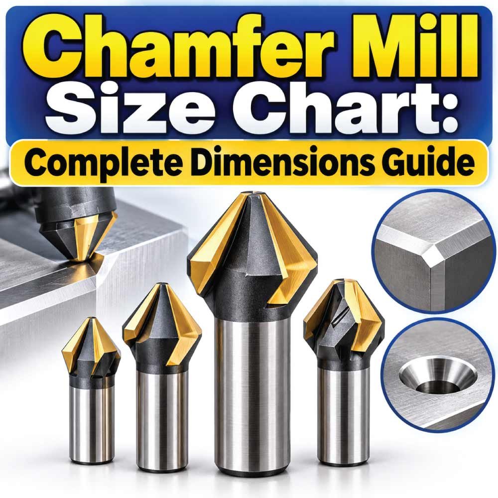
Choosing the correct chamfer mill is important when you need clean edges, consistent bevels, countersink-like features, or controlled edge breaks in machined parts. A cutter that is too large, too small, or has the wrong included angle can produce an incorrect chamfer even when the CNC program or manual setup is otherwise correct.
This Chamfer Mill Size Chart explains the most important cutter dimensions, common diameter ranges, angles, shank sizes, flute configurations, and practical selection factors. It also explains the difference between cutter diameter and chamfer size, how chamfer angles are specified, and how to measure a chamfer mill before machining.
What Is a Chamfer Mill?
A chamfer mill is a cutting tool designed primarily to create an angled edge, bevel, or chamfer on a workpiece. It is commonly used in milling machines, CNC machining centers, drill presses equipped for milling, and other machining setups.
Unlike a conventional end mill, the cutting geometry of a chamfer mill is designed around an angled cutting surface. Depending on its design, it may be used for:
- Breaking sharp edges
- Creating external chamfers
- Preparing holes and openings
- Deburring machined edges
- Creating angled profiles
- Preparing surfaces for welding or assembly
- Producing countersink-style features
- Finishing previously machined edges
Chamfer mills are available in carbide, high-speed steel (HSS), and other tool materials, with configurations selected according to workpiece material, machine capability, production requirements, and cutting conditions.
The most important specifications usually include cutter diameter, included angle, shank diameter, overall length, flute count, and cutting length.
Chamfer Mill Size Chart
There is no single universal dimensional chart covering every chamfer mill because manufacturers offer different combinations of cutting diameter, shank diameter, overall length, angle, and flute configuration. The following chart shows common nominal cutter diameters encountered in inch and metric tooling rather than claiming that every size is standardized across manufacturers.
Common Metric Chamfer Mill Diameters
| Cutter Diameter | Common Use | Typical Setup Consideration |
|---|---|---|
| 4 mm | Small edge work | Requires controlled feed and setup |
| 6 mm | Small components | Useful for limited-access areas |
| 8 mm | General light machining | Good for smaller parts |
| 10 mm | General-purpose work | Common intermediate size |
| 12 mm | General machining | Suitable for many workpieces |
| 16 mm | Larger edge work | Provides broader cutting coverage |
| 20 mm | Heavy edge work | Requires adequate machine clearance |
| 25 mm | Large chamfers | Useful where larger geometry is required |
| 32 mm | Large components | Requires appropriate tool holding |
These diameters describe the nominal cutting diameter, not the width of the finished chamfer. The actual chamfer width depends on the cutter angle and how deeply the tool enters the workpiece.
Common Inch Chamfer Mill Diameters
| Cutter Diameter | Approx. Metric Equivalent | Typical Application |
|---|---|---|
| 1/4 in | 6.35 mm | Small parts and edge breaking |
| 3/8 in | 9.53 mm | Light general machining |
| 1/2 in | 12.70 mm | General-purpose machining |
| 5/8 in | 15.88 mm | Medium-sized components |
| 3/4 in | 19.05 mm | Larger edge work |
| 1 in | 25.40 mm | Large chamfers and components |
| 1-1/4 in | 31.75 mm | Large-feature machining |
Availability varies by tool manufacturer, cutter style, angle, coating, and shank configuration. Always compare the complete tool specification rather than selecting a cutter based only on diameter.
Chamfer Mill Dimensions You Need to Know
A chamfer mill’s diameter is only one part of its geometry. Several dimensions determine whether a particular cutter will fit the machine and produce the required feature.
Cutter Diameter
The cutter diameter is the maximum diameter across the cutting portion of the tool. It affects the area of the workpiece contacted by the cutter and the geometry available for producing a chamfer.
A larger cutter is not automatically better. The required diameter depends on the feature size, available clearance, machine rigidity, and tool geometry.
Shank Diameter
The shank diameter is the cylindrical portion held by the tool holder or collet.
Common shank sizes include configurations such as:
- 1/4 inch
- 3/8 inch
- 1/2 inch
- 5/8 inch
- 3/4 inch
- 6 mm
- 8 mm
- 10 mm
- 12 mm
- 16 mm
The shank must match the available holder or collet. A cutter with the correct cutting diameter can still be unsuitable if its shank does not fit the tooling system.
Overall Length
Overall length is the distance from the end of the shank to the furthest cutting point of the tool.
A longer tool may provide additional reach, but excessive stickout can increase deflection and vibration. For rigid machining, the practical goal is generally to use enough reach without unnecessarily extending the cutter.
Cutting Length
Cutting length indicates how much of the tool’s geometry is intended to engage the workpiece.
The required cutting length depends on the depth and shape of the chamfer, workpiece geometry, and cutter design.
Included Angle
The included angle is one of the most important chamfer mill specifications.
Common tool angles include 60°, 90°, and 120° included-angle configurations, along with other specialized geometries.
A particularly important point is that the included angle should not automatically be interpreted as the angle of the finished chamfer relative to the top surface.
For a symmetrical 90° included-angle cutter, each side of the cutting profile is generally positioned at 45° to the tool centerline. This distinction matters when calculating the resulting chamfer geometry.
Chamfer Mill Angle Chart
Chamfer mills are often selected by their included angle because the angle determines the shape of the machined bevel.
| Included Angle | Approx. Half-Angle | Common Purpose |
|---|---|---|
| 60° | 30° | Specialized angled features |
| 90° | 45° | General chamfering and edge breaking |
| 120° | 60° | Specialized profiles and edge work |
The exact application depends on the cutter design and the geometry required on the workpiece.
Why 90° Chamfer Mills Are Common
A 90° included-angle chamfer mill is widely useful because it produces a symmetrical 45° cutting relationship around the tool axis.
It can be used for:
- Edge chamfering
- Deburring
- Hole-edge finishing
- Countersink-style operations
- General CNC edge preparation
However, a 90° cutter should not be selected simply because it is common. The required workpiece geometry should determine the tool angle.
How Chamfer Mill Size Relates to Chamfer Width
One of the most common mistakes is assuming that a 12 mm chamfer mill creates a 12 mm chamfer.
It does not.
The 12 mm measurement describes the cutter’s nominal diameter, while the finished chamfer width depends on the cutter angle and depth of engagement.
For a symmetrical chamfer, the relationship between chamfer width, vertical depth, and tool angle can be considered geometrically. For a 45° chamfer, for example, equal horizontal and vertical distances are produced in the idealized cross-section.
This means a programmer or machinist should establish the required finished chamfer dimension first, then determine the appropriate tool position and depth.
Types of Chamfer Mills
Different chamfer mill designs are intended for different machining conditions. Understanding the tool type helps prevent selecting a cutter based solely on size.
Single-Flute Chamfer Mill
Single-flute designs can provide a large chip space and are sometimes used where chip evacuation is important.
They may be suitable for certain materials and machining conditions, but the correct cutting parameters depend on the specific cutter geometry and workpiece.
Two-Flute Chamfer Mill
Two-flute tools provide more cutting edges than a single-flute design while retaining relatively open flute space.
They can be useful for general machining and edge finishing.
Multi-Flute Chamfer Mill
Tools with additional flutes can provide more cutting edges per revolution. They may be useful when the application benefits from higher feed rates or particular finishing characteristics.
The tradeoff is that increased flute count can reduce available chip space.
Carbide Chamfer Mill
Carbide chamfer mills are commonly selected for rigid CNC machining and demanding production applications.
Advantages can include:
- High hardness
- Good wear resistance
- Suitability for high-speed machining
- Consistent cutting performance when properly applied
Carbide tools are relatively brittle, so excessive vibration, tool overhang, or incorrect cutting conditions can damage the cutting edges.
HSS Chamfer Mill
HSS chamfer mills are useful in many general-purpose machining situations and can be more forgiving in some manual machining applications.
They are often considered where:
- Cutting speeds are moderate
- Tool cost matters
- Manual machining is involved
- A tougher cutting edge is desirable
The correct choice depends on material, machine, production volume, and required surface finish.
How to Choose the Correct Chamfer Mill Size
Selecting the cutter should begin with the required finished feature, not the cutter diameter alone.
1. Determine the Required Chamfer
First identify the desired chamfer dimensions.
For example, a drawing might specify a chamfer such as:
- 0.5 × 45°
- 1 × 45°
- 2 × 45°
- 1 mm × 30°
- A specified countersink diameter and angle
The drawing’s terminology and tolerances should be followed exactly.
2. Select the Correct Angle
Choose the tool angle that matches the required geometry.
If the drawing calls for a particular countersink or chamfer angle, the cutter’s included angle must be compatible with that requirement.
Do not confuse:
Tool included angle → Workpiece chamfer angle → Countersink angle
These terms can describe related but different measurements.
3. Check Cutter Diameter
Choose a cutter diameter that provides sufficient cutting geometry while fitting around the workpiece.
A small cutter may be appropriate for tight areas, while a larger cutter may offer greater rigidity for larger features.
4. Match the Shank
Confirm that the shank fits the machine’s holder, collet, or chuck.
For CNC work, also consider the holder system, gauge length, available clearance, and machine spindle limitations.
5. Consider Tool Reach
Use the shortest practical tool that reaches the feature.
Excessive stickout can contribute to:
- Deflection
- Chatter
- Poor surface finish
- Dimensional inconsistency
- Premature tool wear
6. Select the Appropriate Material
The cutter material should match the workpiece and machining conditions.
For example, carbide may be appropriate for rigid production machining, while HSS can be practical for certain general-purpose operations.
Also Read:
How to Measure a Chamfer Mill
If the cutter’s packaging or markings are unavailable, several dimensions can be checked manually.
Measure the Cutter Diameter
Use a micrometer or suitable caliper to measure the maximum diameter of the cutting section.
Take care not to measure an unrelated portion of the tool.
Measure the Shank
Measure the cylindrical shank with an appropriate precision measuring instrument.
Compare the result with the holder’s required size.
Measure the Overall Length
Place the cutter on a flat reference surface and measure from the shank end to the furthest cutting point.
Remember that overall length does not necessarily equal the usable cutting length.
Identify the Angle
The angle should ideally be confirmed from the manufacturer’s tool specification or an accurate inspection method.
Estimating a small angular difference visually can lead to incorrect tool selection.
For precision work, use the tool’s documented specification rather than relying on a rough measurement.
Also Read:
Chamfer Mill Size Selection by Application
Different machining jobs require different combinations of diameter, angle, reach, and rigidity.
| Application | Typical Tool Consideration | Important Factor |
|---|---|---|
| Small edge break | Small-diameter cutter | Access and control |
| General CNC chamfering | Medium-diameter cutter | Rigidity and consistency |
| Large component | Larger cutter | Clearance and machine capacity |
| Hole chamfering | Appropriate-angle cutter | Finished hole geometry |
| Deburring | Small or specialized tool | Controlled material removal |
| Deep-access feature | Extended-reach design | Deflection control |
| Production work | Carbide or production-grade tool | Tool life and repeatability |
| Manual machining | HSS or suitable general tool | Speed and operator control |
These are application guidelines rather than universal tool specifications.
Chamfer Mill vs Countersink
Chamfer mills and countersinks can look similar because both use angled cutting surfaces, but their intended applications can differ.
A chamfer mill is commonly used for creating edge chamfers and angled profiles during milling operations. It can also be used for certain hole-edge operations.
A countersink is specifically designed to create a conical recess, commonly around a hole, for accommodating a countersunk fastener or producing a specified countersink geometry.
The distinction is important because the required geometry may depend on:
- Hole diameter
- Fastener head geometry
- Included angle
- Required countersink diameter
- Depth
- Surface finish
- Positional accuracy
When a drawing specifies a countersink, use a tool designed and specified for that application unless the machining process explicitly permits another cutter.
Also Read:
Chamfer Mill vs End Mill
A standard end mill has a different primary cutting geometry from a chamfer mill.
An end mill is generally used for operations such as:
- Slotting
- Pocketing
- Profiling
- Contouring
- Face-related milling operations
A chamfer mill is designed around its angled cutting profile.
Using an end mill to create a simple edge break may be possible in some machining strategies, but it is not equivalent to using a properly selected chamfer tool.
The correct tool depends on the feature, tolerance, machine, material, and required production process.
Common Chamfer Mill Mistakes
Even with the correct nominal cutter size, machining problems can occur when other dimensions are overlooked.
Choosing the Cutter Diameter as the Chamfer Size
A 10 mm chamfer mill does not automatically produce a 10 mm chamfer.
Always calculate or verify the actual tool engagement needed for the specified feature.
Confusing Included Angle and Edge Angle
A tool advertised as 90° generally refers to its included angle. The corresponding angle of an individual side relative to the centerline is different.
Always check how the manufacturer defines the angle.
Using Excessive Tool Stickout
Long extension increases flexibility and can make a seemingly simple chamfer operation unstable.
Keep the tool extension as short as practical.
Ignoring Workpiece Clearance
A cutter may have the correct diameter but still interfere with adjacent surfaces.
Check the complete cutter profile and workpiece geometry before machining.
Using Incorrect Cutting Parameters
Feed, speed, depth of cut, and coolant requirements depend on the tool material, workpiece, machine, cutter geometry, and manufacturer recommendations.
Avoid transferring cutting parameters from one chamfer mill to another without checking their specifications.
Measuring the Wrong Dimension
Tool catalogs may list:
- Cutting diameter
- Shank diameter
- Overall length
- Cutting length
- Neck diameter
- Included angle
These dimensions are not interchangeable.
How to Get a Clean Chamfer
A clean chamfer requires more than selecting the right nominal size.
Use a Rigid Setup
Secure the workpiece properly and minimize vibration. Rigidity becomes especially important with larger cutters or hard materials.
Minimize Tool Overhang
Keep the distance between the holder and cutting area as short as practical.
Verify Tool Runout
Excessive runout can cause uneven cutting, premature wear, and inconsistent chamfer dimensions.
Use Appropriate Cutting Conditions
Follow the cutter manufacturer’s recommended cutting data when available. Material type, hardness, cutter coating, flute count, and machine rigidity all affect the suitable parameters.
Inspect the First Part
For production work, measure the first machined feature before continuing with a larger batch.
Check:
- Chamfer width
- Angle
- Surface finish
- Position
- Adjacent dimensions
- Burr formation
This can prevent an incorrect setup from being repeated across multiple parts.
Chamfer Mill Materials and Coatings
Tool material affects performance and should be considered alongside cutter size.
HSS
HSS is widely used for general-purpose cutting tools and can be suitable for many manual and moderate-speed machining applications.
Its combination of toughness and versatility makes it useful where extremely high cutting speeds are not required.
Solid Carbide
Solid carbide is frequently used for CNC machining applications requiring high wear resistance and dimensional consistency.
It performs best when the machine and workholding provide adequate rigidity.
Coated Tools
Coatings can be selected to improve wear resistance and cutting performance for particular machining conditions.
The appropriate coating depends on factors such as:
- Workpiece material
- Cutting speed
- Temperature
- Tool material
- Production requirements
A coating should not be treated as a substitute for correct tool geometry or appropriate cutting parameters.
Metric vs Inch Chamfer Mill Sizes
Metric and inch tooling systems both offer a wide range of chamfer mill dimensions.
Metric sizes are normally specified in millimeters, while inch cutters are identified using fractional or decimal inch dimensions.
When converting between them, remember that a nominal metric size and a nominal inch size are not necessarily exact equivalents.
For example:
1/2 inch = 12.7 mm
Therefore, a 12 mm cutter and a 1/2-inch cutter are close in diameter but are not identical.
The same principle applies to shanks. A holder intended for a 12 mm shank should not automatically be treated as interchangeable with a 1/2-inch shank.
Chamfer Mill Selection Checklist
Before purchasing or installing a chamfer mill, verify the following specifications:
- Cutter diameter
- Included angle
- Shank diameter
- Overall length
- Cutting length
- Number of flutes
- Tool material
- Coating
- Workpiece material
- Machine compatibility
- Tool-holder compatibility
- Required chamfer dimensions
- Available clearance
- Required surface finish
For critical machining work, compare the complete tool specification with the engineering drawing and manufacturer’s documentation.
Frequently Asked Questions About Chamfer Mill Sizes
What is the most common chamfer mill angle?
A 90° included-angle chamfer mill is a common general-purpose configuration. It creates a symmetrical 45° relationship on each side of the cutter axis, making it useful for many conventional edge-chamfering applications.
What size chamfer mill should I use?
Select the cutter based on the required chamfer geometry, available clearance, tool-holder compatibility, workpiece material, machine rigidity, and required reach. Cutter diameter alone should not determine the selection.
Is a chamfer mill the same as a countersink?
Not necessarily. A chamfer mill is primarily intended for milling angled edges and profiles, while a countersink is designed specifically for producing a conical recess, commonly around a hole.
What does a 90 degree chamfer mill mean?
It normally refers to the 90° included angle of the cutter. For a symmetrical tool, each side of the cutting profile is approximately 45° relative to the centerline.
How is chamfer width measured?
Chamfer width is measured on the workpiece according to the drawing’s specified reference surfaces. It should not be confused with the cutter’s outside diameter.
Can a chamfer mill be used for deburring?
Yes. Chamfer mills can be used for controlled edge breaking and deburring when the cutter geometry, workpiece material, and machining method are appropriate.
Are carbide chamfer mills better than HSS?
Neither material is universally better. Carbide can be advantageous for rigid, higher-performance machining, while HSS can be useful for many general-purpose applications. The appropriate choice depends on the machine, material, speed, production requirements, and tool geometry.
How do I know which shank size I need?
The shank must be compatible with the machine’s tool holder, collet, chuck, or other holding system. Check the holder specification before selecting the cutter.
Final Takeaway
A Chamfer Mill Size Chart is useful for comparing cutter diameters, angles, shank dimensions, and tool configurations, but the correct cutter cannot be selected from diameter alone. The finished chamfer geometry, included angle, tool reach, workpiece material, machine rigidity, and holder compatibility all matter.
For general machining, start by identifying the required chamfer from the engineering drawing. Then select the appropriate angle, cutter diameter, shank, tool material, and reach. Finally, verify the manufacturer’s dimensions and cutting recommendations before machining.
Understanding these relationships helps you choose a chamfer mill that fits the machine, reaches the feature safely, and produces the required edge geometry with consistent results.

Engineer Hassan is a Mechanical Engineer with 16+ years of hands-on experience in mechanical hardware, fasteners, and workshop tools. He focuses on size selection, thread identification, and measurement, helping users choose the correct components with accuracy and safety.