
Helical gears are among the most widely used power transmission components in modern machinery because they provide smooth, quiet, and efficient operation compared to spur gears. Their angled teeth allow gradual engagement, reducing vibration, minimizing noise, and increasing load-carrying capacity.
Whether used in industrial gearboxes, automotive transmissions, manufacturing equipment, or heavy machinery, selecting the correct helical gear size is essential for ensuring reliable performance and long service life.
A helical gear size chart serves as a quick reference that helps engineers, technicians, manufacturers, and maintenance professionals identify the proper gear dimensions based on application requirements. Instead of relying solely on calculations, these charts simplify gear selection by presenting standardized measurements, making the design process faster and more accurate.
This complete guide explains everything you need to know about helical gear sizes, including standard dimensions, measurement methods, important terminology, and practical selection tips that help avoid costly installation mistakes.
What Is a Helical Gear and How Does It Work in Power Transmission Systems?
A helical gear is a cylindrical gear with teeth cut at a specific angle relative to the shaft axis. Unlike spur gears, whose teeth are straight, helical gear teeth engage gradually. This progressive contact creates smoother power transmission while significantly reducing operational noise and vibration.
Because several teeth remain in contact simultaneously, helical gears distribute loads more evenly across the gear surface. This design allows them to transmit greater torque while operating at higher speeds.
Helical gears are commonly used in:
- Automotive transmissions
- Industrial gearboxes
- Conveyor systems
- Printing machines
- CNC equipment
- Packaging machinery
- Textile machines
- Food processing equipment
- Heavy-duty manufacturing systems
Their efficiency, durability, and quiet operation make them one of the most preferred gear types in modern engineering.
Why Using a Helical Gear Size Chart Is Important
Choosing the wrong gear size can result in premature wear, excessive noise, poor efficiency, overheating, and even gearbox failure. A helical gear size chart helps eliminate guesswork by providing standardized dimensions that match engineering requirements.
Instead of manually calculating every dimension, engineers use size charts to verify compatibility between gears, shafts, bearings, and gearboxes.
A properly selected helical gear offers several advantages:
- Improved load distribution
- Reduced vibration and noise
- Longer gear life
- Better transmission efficiency
- Lower maintenance costs
- Increased reliability
- Consistent performance under heavy loads
Whether designing new equipment or replacing worn gears, consulting a size chart is considered an engineering best practice.
Understanding Helical Gear Dimensions
Before reading any gear chart, it is important to understand the measurements that define gear size. Every dimension directly affects performance, strength, efficiency, and compatibility with mating gears.
Module (m)
The module represents the size of the gear teeth. It is one of the most important dimensions because mating gears must have the same module.
Typical metric modules include:
| Module (mm) | Common Applications |
|---|---|
| 1 | Small instruments |
| 1.5 | Light machinery |
| 2 | Industrial equipment |
| 2.5 | Medium-duty machines |
| 3 | Automotive systems |
| 4 | Heavy industrial drives |
| 5 | Mining equipment |
| 6+ | Large industrial gearboxes |
Number of Teeth (Z)
The number of teeth determines the gear ratio and rotational speed.
A gear with more teeth generally has:
- Larger pitch diameter
- Lower output speed
- Higher torque
- Improved load distribution
The correct tooth count depends entirely on the required transmission ratio.
Pitch Diameter (D)
Pitch diameter is the imaginary diameter where two mating gears theoretically roll together without slipping.
The basic formula is:
Pitch Diameter = Module × Number of Teeth
For example:
Module = 4 mm
Number of teeth = 30
Pitch Diameter = 120 mm
This dimension is critical for maintaining proper center distance between gears.
Helix Angle (β)
The helix angle refers to the angle of the gear teeth relative to the gear axis.
Common helix angles include:
- 15°
- 20°
- 25°
- 30°
Higher helix angles generally provide:
- Smoother engagement
- Lower noise
- Better load capacity
However, they also create greater axial thrust, requiring stronger bearings.
Face Width (b)
Face width is the width of the gear teeth measured parallel to the gear axis.
A wider face width provides:
- Higher load capacity
- Better wear resistance
- Improved durability
- Longer service life
Most industrial gears use face widths ranging from 20 mm to over 150 mm depending on application requirements.
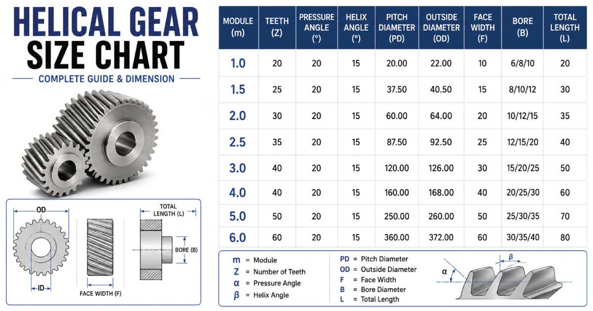
Standard Helical Gear Size Chart
The following chart presents commonly used metric helical gear dimensions found in industrial equipment.
| Module (mm) | Teeth | Pitch Diameter (mm) | Typical Face Width (mm) | Common Applications |
|---|---|---|---|---|
| 1 | 20 | 20 | 10–15 | Instruments |
| 1.5 | 25 | 37.5 | 15–20 | Small machines |
| 2 | 30 | 60 | 20–25 | Conveyor systems |
| 2.5 | 40 | 100 | 25–35 | Packaging machines |
| 3 | 30 | 90 | 30–40 | Automotive gearboxes |
| 4 | 40 | 160 | 40–60 | Industrial machinery |
| 5 | 50 | 250 | 50–80 | Heavy-duty equipment |
| 6 | 60 | 360 | 60–100 | Mining machinery |
| 8 | 70 | 560 | 80–120 | Steel processing plants |
| 10 | 80 | 800 | 100–150 | Large industrial drives |
Note: Actual dimensions may vary depending on manufacturer standards, pressure angle, and specific application requirements.
How to Read a Helical Gear Size Chart Correctly
Many beginners focus only on gear diameter when selecting a helical gear. In reality, every specification in the chart must be compatible with the mating gear and operating conditions.
When reading a gear chart, verify the following information carefully:
- Module
- Number of teeth
- Pitch diameter
- Outside diameter
- Face width
- Helix angle
- Pressure angle
- Bore size
- Keyway dimensions
- Material specification
Ignoring even one of these dimensions may lead to improper meshing, excessive wear, higher operating temperatures, or complete transmission failure. Always compare the chart values with the original equipment specifications or engineering drawings before purchasing a replacement gear.
👉 Discover the latest Tapered Bearing Size Chart along with an Expert Guide and Professional Guide designed to simplify size selection for every mechanical application.
Factors Affecting Helical Gear Size
Selecting the right gear size involves more than matching dimensions. Engineers must evaluate the operating environment, transmitted power, shaft arrangement, and expected service life to ensure the gear performs reliably under real-world conditions.
Some of the most important factors include:
- Required torque output
- Operating speed (RPM)
- Gear ratio
- Motor power
- Shock loading
- Duty cycle
- Shaft size
- Bearing capacity
- Lubrication method
- Operating temperature
- Material strength
- Environmental conditions such as dust, moisture, or corrosive exposure
Considering these factors alongside a standard size chart helps ensure optimal efficiency, reduced maintenance, and a longer operational lifespan.
How to Measure Helical Gears
Measuring a helical gear accurately is essential when replacing a worn gear or designing a new power transmission system. Even a small measurement error can cause improper meshing, excessive noise, premature wear, or gearbox failure. Using precise measuring tools and understanding each gear dimension ensures the replacement gear matches the original specifications and performs efficiently.
The most important dimensions to measure include:
- Outside diameter
- Pitch diameter
- Number of teeth
- Module
- Face width
- Helix angle
- Bore diameter
- Keyway dimensions
For the best results, use precision instruments such as a vernier caliper, micrometer, gear tooth caliper, or coordinate measuring machine (CMM). If the original engineering drawings are available, compare all measurements with the manufacturer’s specifications before ordering a replacement gear.
Common Helical Gear Materials
The material used to manufacture a helical gear has a direct impact on its strength, durability, wear resistance, and operating life. Different industries require different materials depending on load conditions, operating speed, lubrication, and environmental exposure.
Carbon Steel
Carbon steel is commonly used in general industrial applications because it offers good strength and cost-effectiveness. It performs well in moderate-load systems where high hardness is not the primary requirement.
Alloy Steel
Alloy steel is widely used for heavy-duty gearboxes because it provides superior strength, excellent fatigue resistance, and improved toughness. Heat-treated alloy steel gears are commonly found in mining, construction, and automotive transmissions.
Stainless Steel
Stainless steel gears are preferred in food processing, pharmaceutical manufacturing, and marine environments because they offer outstanding corrosion resistance while maintaining good mechanical properties.
Cast Iron
Cast iron gears are suitable for low-speed, heavy-load applications where vibration damping is important. They are frequently used in older industrial machinery and certain agricultural equipment.
Engineering Plastics
Plastic helical gears made from nylon, acetal, or reinforced polymers are ideal for lightweight machinery requiring quiet operation. They are commonly used in office equipment, consumer products, and light-duty automation systems.
Selecting the appropriate material improves gear performance, extends service life, and reduces maintenance costs over the equipment’s operational lifespan.
👉 Don’t guess the correct size. Follow our complete Lag Bolt Size Chart, Expert Guide, and Professional Guide to ensure the perfect fit for your project.
Helical Gear Pressure Angle
The pressure angle is the angle between the gear tooth profile and the line of action where force is transmitted between mating gears. It significantly influences load capacity, gear strength, efficiency, and smoothness of operation.
The most commonly used pressure angles are:
- 20°
- 14.5°
- 25°
Today, the 20-degree pressure angle has become the international standard because it provides an excellent balance between strength, efficiency, and manufacturing simplicity. A larger pressure angle generally increases tooth strength but may also increase bearing loads, while a smaller angle can provide smoother engagement under lighter operating conditions.
When replacing gears, always ensure both mating gears have the same pressure angle to maintain proper contact and efficient power transmission.
Helical Gear vs. Spur Gear Comparison
Although both helical and spur gears perform the same basic function of transmitting power, their designs and operating characteristics are significantly different. Understanding these differences helps engineers select the most suitable gear for specific applications.
| Feature | Helical Gear | Spur Gear |
|---|---|---|
| Tooth Design | Angled teeth | Straight teeth |
| Noise Level | Very low | Higher |
| Load Capacity | High | Moderate |
| Efficiency | Excellent | Very good |
| Speed Capability | High-speed applications | Moderate-speed applications |
| Vibration | Minimal | Higher |
| Manufacturing Cost | Higher | Lower |
| Axial Thrust | Present | None |
| Typical Applications | Automotive, industrial gearboxes | Simple machinery, conveyors |
Helical gears are generally preferred where smooth, quiet, and continuous operation is required, while spur gears remain a cost-effective choice for simpler, lower-speed mechanical systems.
Helical Gear Selection Mistakes
Choosing the wrong helical gear size is one of the most common causes of gearbox problems and unexpected equipment downtime. Careful evaluation of all gear specifications helps prevent expensive repairs and operational failures.
Some of the most common mistakes include:
- Selecting the wrong module
- Ignoring the helix angle
- Choosing an incorrect pressure angle
- Using incompatible bore dimensions
- Overlooking face width requirements
- Ignoring shaft alignment
- Selecting the wrong material for the operating environment
- Failing to consider transmitted torque
- Ordering gears based only on outside diameter
Avoiding these errors helps improve transmission efficiency, reduce maintenance requirements, and increase the reliability of mechanical systems.
👉 Whether you’re replacing or installing a component, our Threaded Rod Size Chart offers an Expert Guide and Professional Guide to make the right selection with confidence.
Industrial Helical Gear Applications
Helical gears are found in countless industries due to their ability to operate quietly while transmitting high loads at high speeds. Their versatility makes them suitable for both precision machinery and heavy industrial equipment.
Common applications include:
- Automotive transmissions
- Industrial gearboxes
- Cement plants
- Steel rolling mills
- Mining equipment
- Material handling systems
- Conveyor drives
- Packaging machinery
- Printing presses
- Textile machines
- Marine propulsion systems
- Agricultural equipment
- Power generation facilities
- Robotics and automation
- Food processing machinery
These applications demonstrate why helical gears remain one of the most reliable and widely used gear types in modern mechanical engineering.
Maintenance Tips That Help Extend the Service Life of Helical Gears
Proper maintenance plays a critical role in maximizing the lifespan of helical gears. Even high-quality gears can fail prematurely if lubrication, alignment, or inspection procedures are neglected. Establishing a preventive maintenance schedule reduces downtime and improves equipment reliability.
Recommended maintenance practices include:
- Inspect gears regularly for wear and pitting.
- Maintain the correct lubricant type and level.
- Monitor operating temperatures.
- Check shaft alignment periodically.
- Replace damaged bearings promptly.
- Remove contamination from lubrication systems.
- Listen for unusual noise or vibration.
- Follow manufacturer maintenance intervals.
Routine inspections allow small issues to be identified before they develop into major mechanical failures, reducing repair costs and improving overall equipment efficiency.
Conclusion
A helical gear size chart is an essential engineering reference that simplifies gear selection and ensures compatibility between mating components. Understanding critical dimensions such as module, pitch diameter, helix angle, pressure angle, face width, and tooth count helps engineers and maintenance professionals choose the right gear for every application.
In addition to using a standardized size chart, factors such as transmitted torque, operating speed, material selection, lubrication, and maintenance practices should always be considered. By following these guidelines, you can improve transmission efficiency, reduce equipment downtime, extend gear life, and ensure reliable performance across a wide range of industrial and mechanical applications.
FAQs:
What is the most important measurement in a helical gear size chart?
The module is generally considered the most important measurement because it determines the size of the gear teeth. Two gears must have the same module to mesh correctly. Other dimensions, including the pressure angle, helix angle, and number of teeth, must also match to ensure smooth and efficient power transmission.
How do I identify the correct replacement helical gear?
Start by measuring the outside diameter, module, number of teeth, face width, bore diameter, and helix angle. Compare these measurements with the manufacturer’s specifications or engineering drawings whenever possible. Matching all critical dimensions ensures proper installation, reliable performance, and a longer service life.
Why are helical gears quieter than spur gears?
Helical gears have angled teeth that engage gradually instead of making full contact instantly. This gradual engagement reduces impact forces, minimizes vibration, and produces much quieter operation. The smoother transfer of power also improves load distribution and extends the lifespan of the gear set.
Can helical gears handle heavier loads than spur gears?
Yes. Because multiple teeth remain engaged simultaneously, helical gears distribute forces more evenly across the gear surface. This allows them to carry higher loads, transmit greater torque, and operate at higher speeds while maintaining smooth and reliable performance.
Which industries use helical gears the most?
Helical gears are extensively used in automotive manufacturing, industrial machinery, mining equipment, steel production, packaging systems, food processing, marine propulsion, robotics, agricultural equipment, and power generation because of their high efficiency, durability, and quiet operation.

Engineer Hassan is a Mechanical Engineer with 16+ years of hands-on experience in mechanical hardware, fasteners, and workshop tools. He focuses on size selection, thread identification, and measurement, helping users choose the correct components with accuracy and safety.