
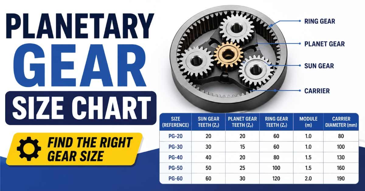
A planetary gear size chart helps engineers, mechanics, manufacturers, and machinery users compare planetary gearbox dimensions, gear ratios, torque capacity, and common applications. Planetary gears are compact transmission systems that can deliver high torque while maintaining a relatively small overall size.
Unlike a simple pair of spur gears, a planetary gear system uses a sun gear, planet gears, ring gear, and planet carrier. These components work together to provide different speed and torque characteristics depending on which member is fixed, driven, or used as the output.
Planetary gear systems are widely used in robotics, automotive transmissions, industrial machinery, electric motors, automation equipment, wind turbines, aerospace systems, and power tools.
Because planetary gearboxes are available in many configurations, there is no single universal size chart covering every manufacturer. Gearbox frame sizes, outside diameters, lengths, ratios, torque ratings, and mounting dimensions vary by design.
This guide explains planetary gear sizes, planetary gearbox dimensions, gear ratios, torque ratings, stages, sizing factors, applications, and how to select the right planetary gear system.
What Is a Planetary Gear?
A planetary gear system is a compact gear arrangement consisting of several gears that rotate around a central gear.
The main components are:
- Sun gear – The central gear.
- Planet gears – Gears that rotate around the sun gear.
- Planet carrier – Holds the planet gears and allows them to orbit the sun.
- Ring gear – The outer gear with internal teeth.
The arrangement resembles planets orbiting the sun, which is why the system is called a planetary gear.
Depending on the operating configuration, the sun gear, ring gear, or carrier can act as the input, output, or stationary member.
This flexibility allows planetary gearboxes to provide different gear ratios while keeping the transmission compact.
Planetary Gear Size Chart
Planetary gear sizes are often described using gearbox frame size, outside diameter, output torque, and overall length rather than a single gear diameter.
The following chart provides representative planetary gearbox size ranges for general comparison. Actual specifications vary significantly between manufacturers and models.
| Planetary Gearbox Size | Approx. Outer Diameter | Typical Output Torque Range | Common Applications |
|---|---|---|---|
| Micro | 10–25 mm | Up to 0.5 N·m | Miniature mechanisms |
| Small | 20–50 mm | 0.2–10 N·m | Robotics, instruments |
| Medium | 40–100 mm | 5–200 N·m | Automation, machinery |
| Large | 80–180 mm | 100–2,000 N·m | Industrial equipment |
| Heavy Duty | 150–400+ mm | 1,000–100,000+ N·m | Heavy machinery |
These ranges are general engineering references, not universal industry standards. A gearbox with a particular outside diameter may have a very different torque rating depending on its gear geometry, materials, bearings, lubrication, reduction ratio, and manufacturer.
Planetary Gearbox Dimensions Explained
When comparing planetary gearbox sizes, several dimensions should be considered.
Outside Diameter
The outside diameter is the overall diameter of the gearbox housing or gear assembly.
A larger housing generally provides space for:
- Larger gears
- Larger bearings
- Greater tooth width
- Higher torque capacity
- Improved heat dissipation
However, housing size alone cannot be used to determine gearbox capacity.
Overall Length
Overall length is important when installation space is limited.
Planetary gearboxes can be relatively short compared with other reduction systems because multiple gears share the transmitted load.
Input Diameter
The input shaft or input interface must match the motor or driving mechanism.
Common input configurations include:
- Solid shafts
- Hollow shafts
- Keyed shafts
- Splined shafts
- Flanged motor interfaces
Output Diameter
The output shaft must be capable of transmitting the required torque without excessive deflection.
Large planetary gearboxes generally use larger output shafts and bearings for demanding applications.
Mounting Dimensions
Mounting dimensions may include:
- Bolt-circle diameter
- Mounting-hole size
- Flange diameter
- Pilot diameter
- Shaft center height
These dimensions are particularly important when replacing an existing gearbox.
Planetary Gear Ratio Chart
Gear ratio is one of the most important specifications when selecting a planetary gearbox.
Common reduction ratios include:
| Planetary Gearbox Type | Common Ratio Range | Typical Use |
|---|---|---|
| Single Stage | 3:1–10:1 | Moderate speed reduction |
| Two Stage | 9:1–100:1 | General speed reduction |
| Three Stage | 27:1–1,000:1 | High reduction |
| Four Stage | 80:1–10,000+:1 | Very high reduction |
The available ratio range depends on the number of stages and the tooth counts selected for the sun, planet, and ring gears.
Multi-stage planetary gearboxes can achieve very high reduction ratios while maintaining a relatively compact design.
How Planetary Gear Ratios Work
Planetary gear ratios depend on which member is fixed and which members are used as input and output.
For a basic planetary arrangement, the relationship between the sun gear, ring gear, and carrier can be expressed using the Willis equation:
Nₛωₛ + Nᵣωᵣ = (Nₛ + Nᵣ)ωc
Where:
- Nₛ = number of sun gear teeth
- Nᵣ = number of ring gear teeth
- ωₛ = sun gear speed
- ωᵣ = ring gear speed
- ωc = carrier speed
This relationship allows different operating configurations to produce different speed ratios.
Ring Gear Fixed
When the ring gear is stationary and the sun gear is driven, the carrier can provide a reduced-speed output.
This is one of the most common configurations in planetary reduction gearboxes.
Sun Gear Fixed
When the sun gear is stationary and the ring gear is driven, the carrier can produce a different ratio and direction relationship.
Carrier Fixed
When the carrier is held stationary, the sun and ring gears rotate relative to one another and the system functions differently from a typical planetary reducer.
Planetary Gear Stage Size Chart
Adding stages increases the overall reduction ratio.
| Number of Stages | Typical Reduction Capability | Main Advantage |
|---|---|---|
| 1 Stage | Low to moderate | Short and efficient |
| 2 Stage | Moderate to high | Good balance |
| 3 Stage | High | Large speed reduction |
| 4+ Stages | Very high | Extremely low output speed |
More stages generally increase gearbox length, weight, cost, and mechanical losses.
For this reason, the ideal gearbox should use only as many stages as necessary to achieve the required output speed and torque.
Planetary Gear Torque Capacity
Torque capacity is another critical part of planetary gear sizing.
A planetary gearbox can distribute load among multiple planet gears. This load-sharing characteristic can allow a compact gearbox to transmit substantial torque.
However, rated torque depends on many factors, including:
- Gear diameter
- Gear width
- Number of planets
- Gear material
- Heat treatment
- Bearing capacity
- Lubrication
- Reduction ratio
- Operating speed
- Duty cycle
- Temperature
- Shock loading
A gearbox should never be selected solely from its physical dimensions.
Nominal Torque
Nominal or rated torque represents the torque the gearbox is designed to handle under specified operating conditions.
Peak Torque
Peak torque is the maximum temporary torque the gearbox can tolerate under specified conditions.
Peak torque should not be confused with continuous rated torque.
Continuous Torque
Continuous torque is the torque the gearbox can transmit continuously without exceeding its thermal or mechanical limitations under the manufacturer’s stated conditions.
Planetary Gear Torque Size Guide
The following table gives a general conceptual comparison rather than a universal standard.
| Gearbox Class | Approx. Torque Category | Typical Applications |
|---|---|---|
| Micro | Less than 1 N·m | Miniature devices |
| Small | 1–20 N·m | Robotics and automation |
| Medium | 20–500 N·m | Industrial machinery |
| Large | 500–5,000 N·m | Heavy equipment |
| Heavy Duty | 5,000+ N·m | Large industrial drives |
Actual ratings must be taken from the manufacturer’s technical documentation for the exact gearbox.
Planetary Gear Teeth and Dimensions
Gear tooth dimensions affect the mechanical characteristics of the planetary system.
Important gear parameters include:
- Number of teeth
- Module
- Diametral pitch
- Pressure angle
- Face width
- Pitch diameter
- Outside diameter
- Root diameter
Module
Metric gears commonly use module to define tooth size.
The basic relationship is:
Module = Pitch Diameter ÷ Number of Teeth
A larger module generally corresponds to larger gear teeth.
Diametral Pitch
In inch-based gear systems, diametral pitch may be used instead of module.
It describes the relationship between the number of teeth and pitch diameter.
Face Width
Face width is the width of the gear teeth along the axis.
Increasing face width can increase load-carrying capability, although other design factors must also be considered.
Planetary Gear Materials
Material selection strongly affects gear strength, wear resistance, and service life.
Alloy Steel
Alloy steel is widely used for industrial planetary gears because of its strength and ability to undergo heat treatment.
Hardened Steel
Hardened gears provide improved resistance to wear and surface damage.
They are commonly used in high-load applications.
Powder Metal
Powder-metal gears may be used in certain high-volume and compact applications.
Their suitability depends on the required torque, precision, speed, and manufacturing process.
Specialized Materials
Some miniature or specialized planetary gear systems may use engineering plastics or composite materials.
These can reduce weight and noise but are generally selected according to application-specific requirements.
Planetary Gearbox Efficiency
Planetary gearboxes are often valued for their combination of compactness, torque density, and efficiency.
Efficiency depends on:
- Number of stages
- Gear tooth geometry
- Bearing losses
- Lubrication
- Operating speed
- Manufacturing accuracy
- Load
- Gearbox design
A single-stage planetary gearbox will generally have fewer sources of mechanical loss than a multi-stage design.
As additional stages are added, total efficiency can decrease because each stage introduces its own losses.
Planetary Gearbox Size Selection Guide
Selecting the correct planetary gearbox requires matching the gearbox to the motor, load, speed, and operating environment.
1. Determine Input Speed
Identify the motor or driving shaft speed.
For example, an electric motor may operate at several thousand revolutions per minute.
2. Determine Required Output Speed
Calculate the output speed needed by the machine.
A basic relationship is:
Gear Ratio = Input Speed ÷ Output Speed
For example, if the input speed is 3,000 RPM and the desired output speed is 300 RPM:
Gear Ratio = 3,000 ÷ 300 = 10:1
A nominal 10:1 reduction would therefore be required, subject to the gearbox’s actual ratio and operating configuration.
3. Determine Required Torque
Calculate or estimate the torque required by the driven load.
Do not forget acceleration, friction, startup loads, and shock loads.
4. Check Service Factor
A service factor provides additional capacity for demanding operating conditions.
Applications involving:
- Frequent starts and stops
- Shock loads
- Reversing
- High temperatures
- Continuous operation
may require a higher-rated gearbox.
5. Check Mounting Space
Verify:
- Gearbox diameter
- Gearbox length
- Shaft size
- Mounting-hole pattern
- Pilot diameter
- Motor interface
6. Consider Backlash
Backlash is the amount of relative movement between mating gear teeth when the direction of motion changes.
Low-backlash planetary gearboxes are often preferred for:
- Robotics
- CNC machinery
- Servo systems
- Precision automation
Discover More:
Planetary Gearbox vs Spur Gearbox
Planetary and spur gearboxes have different characteristics.
| Feature | Planetary Gearbox | Spur Gearbox |
|---|---|---|
| Torque density | High | Moderate |
| Compactness | Excellent | Good |
| Load sharing | Yes | Usually no |
| Efficiency | High | High |
| Complexity | Higher | Lower |
| Cost | Generally higher | Generally lower |
| Precision options | Excellent | Good |
| High reduction | Excellent in stages | Good |
Planetary systems are particularly attractive where high torque must be transmitted through a compact package.
Planetary Gearbox vs Worm Gearbox
Worm gearboxes are often selected for high reduction ratios and certain self-locking applications, while planetary gearboxes are commonly selected for high torque density and efficiency.
| Feature | Planetary | Worm |
|---|---|---|
| Efficiency | Generally high | Often lower |
| Torque density | High | Moderate |
| Compactness | Excellent | Good |
| Heat generation | Generally lower | Can be higher |
| Backdrivability | Often possible | Depends on design |
| High ratio | Excellent with multiple stages | Excellent |
| Typical use | Precision and high torque | Conveyors and positioning |
The best choice depends on the application’s speed, torque, efficiency, backdrivability, and cost requirements.
Discover More:
Planetary Gear Applications
Planetary gear systems are used in many industries.
Automotive
They are used in:
- Automatic transmissions
- Hybrid powertrains
- Electric drive systems
- Differential mechanisms
- Transfer systems
Robotics
Robotic joints frequently use planetary or precision planetary gearboxes because they provide high torque in a compact package.
Industrial Automation
Applications include:
- Servo motors
- Automated machinery
- Packaging equipment
- Material-handling systems
- Machine tools
Wind Turbines
Large planetary gear arrangements can be used in wind turbine drivetrains to increase rotational speed from the turbine rotor to the generator.
Aerospace
Planetary gearing is useful where low weight, high torque density, and compact packaging are important.
Power Tools
Compact planetary gear systems are frequently used in drills, drivers, and other portable equipment.
Planetary Gear Maintenance
Proper maintenance helps extend gearbox service life.
Lubrication
Use the lubricant specified by the gearbox manufacturer.
Incorrect lubricant viscosity or type can increase wear and operating temperature.
Inspection
Regularly inspect for:
- Excessive noise
- Vibration
- Oil leakage
- Overheating
- Shaft movement
- Abnormal backlash
- Reduced output performance
Operating Temperature
Excessive temperature can indicate:
- Overloading
- Insufficient lubrication
- Excessive speed
- Bearing problems
- Gear damage
Investigate unusual temperature increases before continued operation.
Discover More:
Common Planetary Gear Sizing Mistakes
Several mistakes can lead to premature gearbox failure.
Choosing by Diameter Alone
A larger gearbox housing does not automatically guarantee the required torque capacity.
Ignoring Peak Loads
A machine may experience much higher torque during acceleration or sudden stops than during normal operation.
Ignoring Duty Cycle
A gearbox operating continuously requires different consideration from one used intermittently.
Selecting Too Many Stages
Using unnecessary stages can increase size, cost, and mechanical losses.
Ignoring Backlash
Precision machinery may require low-backlash gearing.
Ignoring Thermal Capacity
A gearbox can have sufficient mechanical torque capacity but still be limited by heat generation during continuous operation.
How to Read a Planetary Gearbox Specification
When comparing planetary gearboxes, look for these specifications:
| Specification | What It Tells You |
|---|---|
| Ratio | Speed reduction |
| Rated Torque | Continuous torque capability |
| Peak Torque | Short-term maximum torque |
| Input Speed | Maximum or recommended input speed |
| Efficiency | Mechanical power transmission efficiency |
| Backlash | Rotational clearance |
| Gearbox Diameter | Physical size |
| Gearbox Length | Installation space |
| Weight | Overall mass |
| Mounting Pattern | Installation compatibility |
| Output Shaft | Mechanical connection |
| Service Factor | Application margin |
Reviewing the complete specification is more reliable than comparing a single size or torque number.
Frequently Asked Questions
What is a planetary gear size chart?
A planetary gear size chart compares common gearbox dimensions, ratios, torque ranges, and application categories. Because planetary gearboxes are manufactured in many different designs, there is no single universal size standard. Manufacturer-specific dimensions should always be used for final equipment selection.
How do I choose the correct planetary gearbox size?
Choose a planetary gearbox based on input speed, required output speed, torque, peak loads, duty cycle, service factor, mounting dimensions, backlash, efficiency, and operating environment. The gearbox should provide sufficient continuous and peak torque capacity for the actual machine.
What is a common planetary gear ratio?
Common planetary gearbox reduction ratios include approximately 3:1, 4:1, 5:1, 10:1, 20:1, 50:1, and 100:1, depending on the number of stages and gear tooth configuration. Multi-stage planetary gearboxes can provide substantially higher overall reduction ratios.
Are planetary gearboxes better than spur gearboxes?
Planetary gearboxes can provide higher torque density, compact dimensions, and load sharing compared with many conventional spur gear arrangements. However, they are usually more complex and expensive. A spur gearbox may be preferable where cost, simplicity, or moderate torque is more important.
What determines planetary gearbox torque capacity?
Torque capacity depends on gear size, tooth geometry, face width, material, heat treatment, number of planets, bearings, lubrication, speed, temperature, and gearbox construction. Therefore, torque should be selected from the manufacturer’s rated and peak torque specifications rather than estimated from physical size alone.
What does a 10:1 planetary gearbox mean?
A 10:1 planetary gearbox provides approximately a ten-to-one speed reduction in its specified reduction configuration. For example, an input speed of 3,000 RPM would theoretically correspond to approximately 300 RPM output before considering the exact gearbox ratio, operating configuration, and other losses.
Why are planetary gears so compact?
Planetary gears distribute the transmitted load across multiple planet gears while allowing several gears to operate concentrically. This arrangement provides high torque density and enables substantial reduction ratios within a relatively small package.
Conclusion
A planetary gear size chart is useful for comparing gearbox dimensions, ratios, torque categories, and applications, but there is no single universal planetary gearbox sizing standard. Actual dimensions and performance vary between manufacturers and gear designs.
When selecting a planetary gear system, consider the input speed, output speed, reduction ratio, continuous torque, peak torque, number of stages, mounting dimensions, backlash, efficiency, service factor, and operating environment.
Planetary gearboxes are especially valuable when high torque, compact size, precision, and efficient power transmission are required. Their load-sharing design makes them suitable for demanding applications ranging from robotics and automation to automotive transmissions, industrial machinery, aerospace systems, and power tools.
The most important rule is to avoid choosing a planetary gearbox based solely on its physical size. Always compare the manufacturer’s complete technical specifications and make sure the selected gearbox can safely handle the required speed, torque, duty cycle, and installation conditions.
With the correct planetary gear size, ratio, torque rating, and configuration, a planetary transmission can provide a compact, reliable, and efficient solution for a wide range of mechanical power-transmission applications.

Engineer Hassan is a Mechanical Engineer with 16+ years of hands-on experience in mechanical hardware, fasteners, and workshop tools. He focuses on size selection, thread identification, and measurement, helping users choose the correct components with accuracy and safety.