
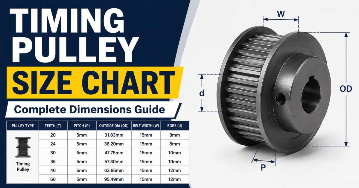
A timing pulley size chart helps you identify the correct pulley size for a synchronous belt drive. Unlike ordinary belt pulleys, timing pulleys use precisely spaced teeth that engage with matching teeth on a timing belt. This positive engagement prevents normal belt slip and allows accurate power and motion transmission.
Timing pulleys are widely used in industrial machinery, CNC machines, robotics, 3D printers, automotive systems, conveyors, packaging equipment, and automated manufacturing equipment. They are available in different tooth counts, pitches, bore sizes, widths, and materials.
Selecting the correct timing pulley requires matching the pulley tooth profile and pitch to the timing belt. Tooth count determines the pulley pitch diameter, while bore size must match the shaft and pulley width must provide adequate belt engagement.
This guide explains timing pulley sizes, tooth counts, pitch diameters, belt profiles, bore dimensions, pulley ratios, materials, applications, and how to select the correct timing pulley.
What Is a Timing Pulley?
A timing pulley is a toothed wheel designed to work with a matching toothed timing belt.
The teeth on the pulley engage with the belt teeth, creating a synchronous drive. Because the belt teeth mesh with the pulley grooves, the system can maintain a precise relationship between input and output shaft rotation.
A typical timing pulley consists of:
- Pulley body
- Toothed circumference
- Bore
- Keyway or other shaft-locking feature
- Flanges on some designs
- Hub on some designs
- Set-screw or clamping arrangement
Timing pulleys are sometimes called synchronous pulleys, toothed pulleys, or timing belt pulleys.
Timing Pulley Size Chart
Timing pulley size is primarily determined by the belt pitch and number of teeth. The pitch diameter can be calculated from these two values.
For a standard timing pulley:
Pitch Diameter = Number of Teeth × Belt Pitch ÷ π
The following chart provides approximate pitch diameters for common pulley tooth counts.
| Tooth Count | 2 mm Pitch | 3 mm Pitch | 5 mm Pitch | 8 mm Pitch |
|---|---|---|---|---|
| 16 Teeth | 10.19 mm | 15.28 mm | 25.46 mm | 40.74 mm |
| 20 Teeth | 12.73 mm | 19.10 mm | 31.83 mm | 50.93 mm |
| 24 Teeth | 15.28 mm | 22.92 mm | 38.20 mm | 61.12 mm |
| 30 Teeth | 19.10 mm | 28.65 mm | 47.75 mm | 76.39 mm |
| 36 Teeth | 22.92 mm | 34.38 mm | 57.30 mm | 91.67 mm |
| 40 Teeth | 25.46 mm | 38.20 mm | 63.66 mm | 101.86 mm |
| 48 Teeth | 30.56 mm | 45.84 mm | 76.39 mm | 122.23 mm |
| 60 Teeth | 38.20 mm | 57.30 mm | 95.49 mm | 152.79 mm |
These values are theoretical pitch diameters. Actual outside diameter, tooth geometry, flange dimensions, and other measurements depend on the specific timing-belt profile.
Understanding Timing Pulley Pitch
Pitch is one of the most important timing pulley dimensions.
What Is Belt Pitch?
Belt pitch is the distance from the center of one belt tooth to the center of the next tooth.
Common metric pitches include:
- 2 mm
- 3 mm
- 5 mm
- 8 mm
- 14 mm
Common inch-based timing belt pitches include:
- 1/5 inch
- 1/4 inch
- 3/8 inch
- 1/2 inch
The pulley pitch must match the belt pitch.
For example, a 5 mm pitch pulley must be used with a compatible 5 mm pitch timing belt.
Why Pitch Matters
If the pulley and belt have different pitches, their teeth will not mesh correctly.
This can cause:
- Poor engagement
- Excessive noise
- Tooth wear
- Belt damage
- Vibration
- Premature failure
Timing Pulley Tooth Count Chart
Tooth count affects both pulley diameter and speed ratio.
| Pulley Teeth | Relative Size | Typical Use |
|---|---|---|
| 12–16 | Very Small | Compact drives |
| 18–24 | Small | General machinery |
| 25–32 | Medium | Automation |
| 36–48 | Medium-Large | Power transmission |
| 50–72 | Large | High-speed reduction systems |
| 80+ | Very Large | Specialized applications |
The minimum recommended tooth count depends on the timing-belt profile, belt manufacturer, speed, torque, and application.
A very small pulley can increase belt flexing and tooth loading, so the smallest possible pulley is not always the best choice.
Timing Pulley Pitch Diameter Chart
The pitch diameter can be calculated from tooth count and pitch.
| Teeth | 3 mm Pitch | 5 mm Pitch | 8 mm Pitch | 10 mm Pitch |
|---|---|---|---|---|
| 18 | 17.19 mm | 28.65 mm | 45.84 mm | 57.30 mm |
| 20 | 19.10 mm | 31.83 mm | 50.93 mm | 63.66 mm |
| 24 | 22.92 mm | 38.20 mm | 61.12 mm | 76.39 mm |
| 28 | 26.74 mm | 44.56 mm | 71.30 mm | 89.13 mm |
| 32 | 30.56 mm | 50.93 mm | 81.49 mm | 101.86 mm |
| 40 | 38.20 mm | 63.66 mm | 101.86 mm | 127.32 mm |
| 48 | 45.84 mm | 76.39 mm | 122.23 mm | 152.79 mm |
| 60 | 57.30 mm | 95.49 mm | 152.79 mm | 190.99 mm |
The pitch diameter is different from the pulley outside diameter. Do not use the outside diameter when calculating the timing-belt speed ratio.
Timing Pulley Bore Size Chart
The bore is the hole through the center of the pulley that fits over the shaft.
Common bore sizes include:
| Bore Size | Approx. Metric Equivalent | Common Application |
|---|---|---|
| 1/4 in | 6.35 mm | Small machinery |
| 5/16 in | 7.94 mm | Small motors |
| 3/8 in | 9.53 mm | Automation |
| 1/2 in | 12.70 mm | Machinery |
| 5/8 in | 15.88 mm | Motor drives |
| 3/4 in | 19.05 mm | Industrial equipment |
| 1 in | 25.40 mm | Larger machinery |
| 1-1/4 in | 31.75 mm | Heavy-duty drives |
Metric bores are also commonly available, such as 5 mm, 6 mm, 8 mm, 10 mm, 12 mm, 15 mm, 20 mm, and 25 mm.
The correct bore must match the shaft or the appropriate bushing system.
Timing Belt Profile and Pulley Compatibility
Timing pulleys must match the belt profile.
Common timing-belt profiles include:
MXL
MXL is a small miniature timing-belt profile commonly used in compact motion systems and instrumentation.
XL
XL belts use a 1/5-inch pitch and are widely used in light-duty motion and power-transmission systems.
L
L timing belts have a 3/8-inch pitch and are used for a range of mechanical applications.
H
H timing belts have a 1/2-inch pitch and are used for heavier power-transmission applications.
HTD Profiles
Common metric HTD profiles include:
- 3M
- 5M
- 8M
- 14M
HTD profiles use a rounded tooth geometry and are widely used in industrial power transmission.
GT Profiles
GT timing belts are commonly used in applications requiring accurate positioning and smooth motion, including robotics and precision machinery.
A pulley designed for one profile should not automatically be used with another profile simply because the pitch appears similar.
Timing Pulley Size Selection Guide
Choosing a timing pulley involves several steps.
1. Identify the Belt Profile
First determine the belt profile.
Check markings on the belt or the manufacturer’s documentation.
2. Determine the Belt Pitch
Identify the distance between adjacent belt teeth.
For example:
- 3M = 3 mm pitch
- 5M = 5 mm pitch
- 8M = 8 mm pitch
3. Select Tooth Count
Choose the number of pulley teeth based on:
- Required speed ratio
- Available space
- Torque
- Belt wrap
- Minimum recommended pulley size
4. Determine Bore Size
Match the pulley bore to the shaft diameter.
If a pulley uses a bushing or locking system, select the correct compatible component.
5. Select Pulley Width
The pulley width must accommodate the belt width and provide proper alignment.
6. Check Material
Choose a material suitable for the speed, torque, temperature, and environmental conditions.
Timing Pulley Speed Ratio
Timing pulleys can change shaft speed by using different tooth counts.
The basic relationship is:
Speed Ratio = Driven Pulley Teeth ÷ Driving Pulley Teeth
For example, if the driving pulley has 20 teeth and the driven pulley has 40 teeth:
Speed Ratio = 40 ÷ 20 = 2:1
The driven shaft rotates at approximately half the speed of the driving shaft, assuming negligible slip and other losses.
Example
Suppose:
- Driver = 20 teeth
- Driven pulley = 60 teeth
- Input speed = 1,800 RPM
The approximate output speed is:
1,800 × 20 ÷ 60 = 600 RPM
Therefore, the output speed is approximately 600 RPM.
Timing Pulley Ratio Chart
| Driver Teeth | Driven Teeth | Approx. Ratio | Output Speed From 1,800 RPM |
|---|---|---|---|
| 20 | 20 | 1:1 | 1,800 RPM |
| 20 | 30 | 1.5:1 | 1,200 RPM |
| 20 | 40 | 2:1 | 900 RPM |
| 20 | 50 | 2.5:1 | 720 RPM |
| 20 | 60 | 3:1 | 600 RPM |
| 20 | 80 | 4:1 | 450 RPM |
| 20 | 100 | 5:1 | 360 RPM |
This chart assumes the 20-tooth pulley is the driver.
Discover More:
Timing Pulley Width
Pulley width should be selected according to the belt width and application requirements.
Common belt widths vary considerably by belt profile and manufacturer.
A pulley that is too narrow may not fully support the belt. A pulley that is unnecessarily wide can increase cost and package size.
When selecting width, consider:
- Belt width
- Required power
- Shaft alignment
- Available space
- Flange configuration
- Manufacturer recommendations
Timing Pulley Materials
Timing pulleys are available in several materials.
Aluminum
Aluminum pulleys are popular because they are:
- Lightweight
- Corrosion resistant
- Easy to machine
- Suitable for many automation applications
They are commonly used in CNC machines, robotics, and motion-control systems.
Steel
Steel timing pulleys provide high strength and durability.
They are commonly used in:
- Industrial machinery
- High-load drives
- Automotive systems
- Heavy-duty power transmission
Stainless Steel
Stainless steel pulleys provide improved corrosion resistance and may be suitable for demanding environments.
Engineering Plastics
Plastic timing pulleys can reduce weight and operating noise.
They are commonly used in:
- Printers
- Small machines
- Robotics
- Consumer equipment
Material selection should consider load, speed, temperature, wear, and environmental exposure.
Timing Pulley Flanges
Some timing pulleys include flanges on one or both sides.
The purpose of a flange is to help keep the timing belt from moving laterally off the pulley.
Flanges can be particularly useful when:
- Shaft alignment may vary
- The belt runs vertically
- The drive has limited lateral guidance
- The pulley arrangement requires additional belt tracking control
However, correct shaft and pulley alignment remains essential even when flanges are present.
Timing Pulley Applications
Timing pulleys are used in many mechanical systems.
CNC Machines
Timing-belt systems can transmit rotary motion accurately between motors and driven components.
Robotics
Timing pulleys are frequently used in robotic and automated mechanisms where synchronized movement is required.
3D Printers
Small timing pulleys and belts are widely used to transfer motor motion to printer axes.
Automotive Systems
Timing belts and pulleys are used in various automotive systems, including engine timing applications and accessory drives, depending on the vehicle design.
Conveyors
Synchronous belt systems can provide controlled movement in conveyor and material-handling equipment.
Packaging Machinery
Timing pulley systems can synchronize rollers, indexing mechanisms, and other moving components.
Discover More:
Timing Pulley Installation
Proper installation is important for reliable timing-belt operation.
Step 1: Inspect the Components
Check the pulley, belt, shaft, key, bushing, and fasteners for damage.
Step 2: Clean the Shaft
Remove dirt, oil, corrosion, and burrs from the shaft and bore.
Step 3: Install the Pulley
Position the pulley on the shaft and install the appropriate key, bushing, or locking mechanism.
Step 4: Align the Pulleys
The pulleys should be aligned so the belt runs straight.
Misalignment can cause:
- Belt-edge wear
- Noise
- Tracking problems
- Uneven tooth loading
- Premature failure
Step 5: Install the Belt
Place the belt over the pulleys without forcing or twisting it.
Step 6: Set Belt Tension
Adjust belt tension according to the belt manufacturer’s specifications.
Excessive tension can overload bearings, while insufficient tension can cause poor engagement or tooth jumping.
Common Timing Pulley Problems
Tooth Skipping
Tooth skipping can result from insufficient tension, overload, incorrect pulley selection, or poor belt engagement.
Belt Wear
Premature belt wear may indicate:
- Misalignment
- Excessive tension
- Contamination
- Incorrect pulley profile
- Damaged pulley teeth
Pulley Noise
Unusual noise can result from poor alignment, incorrect tension, damaged teeth, or incompatible belt and pulley profiles.
Belt Tracking Problems
If the belt repeatedly moves sideways, check pulley alignment, shaft positioning, flanges, and belt condition.
Timing Pulley Maintenance
Timing pulley systems generally require relatively little maintenance when correctly installed.
Regularly inspect:
- Pulley teeth
- Belt teeth
- Belt tension
- Shaft alignment
- Flanges
- Bore and keyway
- Fasteners
- Signs of wear or contamination
Replace worn belts and damaged pulleys together when necessary to restore proper tooth engagement.
Discover More:
Timing Pulley vs V-Belt Pulley
Timing pulleys and V-belt pulleys operate differently.
| Feature | Timing Pulley | V-Belt Pulley |
|---|---|---|
| Belt type | Toothed belt | V-belt |
| Positive engagement | Yes | No |
| Normal belt slip | Very low | Possible |
| Synchronization | Excellent | Limited |
| Maintenance | Generally low | Moderate |
| Common use | Precision drives | General power transmission |
Timing pulleys are preferred when maintaining a fixed relationship between input and output shaft rotation is important.
How to Read a Timing Pulley Size
Timing pulley specifications often contain several pieces of information.
For example, a designation might identify:
- Belt profile
- Number of teeth
- Belt width
- Bore size
- Keyway
- Hub style
A pulley described as a 5M 20-tooth pulley generally indicates a pulley designed for a 5 mm pitch belt with 20 teeth.
However, exact designation systems differ between manufacturers.
Always confirm the manufacturer’s part-number key before ordering a replacement.
Frequently Asked Questions
How do I choose the correct timing pulley size?
Choose a timing pulley by matching the belt profile, pitch, tooth count, bore, width, shaft size, speed, and torque requirements. The pulley must use the same tooth profile and pitch as the timing belt. Manufacturer specifications should be checked before final selection.
How is timing pulley diameter calculated?
The theoretical pitch diameter is calculated using Pitch Diameter = Number of Teeth × Belt Pitch ÷ π. For example, a 20-tooth pulley with a 5 mm pitch has a theoretical pitch diameter of approximately 31.83 mm.
Does a larger timing pulley increase speed?
A larger driven pulley generally reduces output speed when paired with a smaller driving pulley. The speed relationship depends on the tooth counts. A larger pulley can also affect belt wrap, torque transmission, and the physical size of the drive.
What is the difference between pitch diameter and outside diameter?
Pitch diameter is based on the belt’s pitch line and is used for calculating the timing-drive ratio. Outside diameter measures the physical outer surface of the pulley. These dimensions are not normally the same, so they should not be substituted for one another.
Can I use any timing belt with a timing pulley?
No. The belt and pulley must have compatible pitch and tooth profile. A 5M pulley, for example, requires a compatible 5 mm pitch belt with the appropriate tooth geometry. Using incompatible components can result in poor engagement and premature wear.
What is the most common timing pulley pitch?
There is no single universal pitch. Common profiles include 2 mm, 3 mm, 5 mm, 8 mm, and 14 mm metric pitches, along with several inch-based profiles. The appropriate pitch depends on the belt system, load, speed, and application.
Why does timing pulley tooth count matter?
Tooth count affects the pulley pitch diameter and therefore the speed ratio. A smaller driver combined with a larger driven pulley reduces output speed, while a larger driver and smaller driven pulley increase output speed, subject to the limitations of the belt system.
Conclusion
A timing pulley size chart is useful for selecting and comparing pulleys for synchronous belt drives. The most important specifications are belt profile, pitch, tooth count, pitch diameter, bore size, pulley width, material, and shaft connection.
The pulley and timing belt must always be compatible. Matching only the nominal pitch is not necessarily enough because different belt profiles can use different tooth geometries.
When sizing a timing pulley, first identify the belt profile and pitch. Then select the appropriate tooth count based on the required speed ratio, torque, available space, and recommended minimum pulley size. Finally, verify the bore, width, hub, keyway, flange configuration, and mounting method.
Proper alignment and belt tension are equally important. A correctly selected and installed timing pulley system can provide accurate synchronization, reliable power transmission, low slip, and long service life across applications ranging from robotics and CNC machinery to automotive and industrial equipment.

Engineer Hassan is a Mechanical Engineer with 16+ years of hands-on experience in mechanical hardware, fasteners, and workshop tools. He focuses on size selection, thread identification, and measurement, helping users choose the correct components with accuracy and safety.