
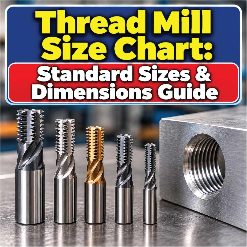
A thread mill size chart helps machinists match the required internal or external thread specification with a suitable CNC thread milling tool. Unlike a conventional tap, a thread mill cuts the thread through controlled circular interpolation, making cutter diameter, thread pitch, thread depth, flute configuration, and machine capability important parts of tool selection.
Thread mills are available for metric, Unified inch, pipe, and other thread forms, with designs ranging from single-profile cutters to multi-form tools. Because cutter dimensions are not universally standardized across manufacturers, the thread specification and the actual tool dimensions should be considered separately.
This guide explains common thread sizes, thread mill types, cutter dimensions, sizing principles, measurement methods, applications, and practical selection considerations.
What Is a Thread Mill?
A thread mill is a rotary cutting tool used on a CNC machine to produce threads by moving the cutter along a helical toolpath. Instead of cutting the complete thread with a straight plunge like a tap, the machine controls the cutter’s circular and axial movement to generate the thread profile.
Thread milling can be used for both internal and external threads, depending on the cutter design and machining setup.
A typical thread milling operation involves:
- Positioning the cutter inside or around the workpiece.
- Entering the material at a controlled depth.
- Moving in a circular interpolation path.
- Advancing axially by the thread pitch.
- Repeating the helical movement until the required thread depth is reached.
This method gives the CNC machine considerable control over the finished thread.
Why Thread Mill Size Matters
Choosing a thread mill based only on the nominal thread size can cause problems. A cutter must also have suitable:
- Cutting diameter
- Overall length
- Cutting length
- Shank diameter
- Thread profile
- Pitch or TPI capability
- Number of flutes
- Material and coating
- Minimum hole or outside diameter requirement
The cutter manufacturer’s dimensions remain important because two tools intended for the same thread may have substantially different physical dimensions.
Thread Mill Size Chart for Common Threads
The following chart provides common thread specifications that are frequently encountered in machining. It identifies the nominal thread size and its pitch or threads per inch rather than assigning one universal cutter diameter.
| Thread Type | Nominal Size | Pitch / TPI | Typical Use |
|---|---|---|---|
| Metric | M3 × 0.5 | 0.5 mm | Small components |
| Metric | M4 × 0.7 | 0.7 mm | General machining |
| Metric | M5 × 0.8 | 0.8 mm | Small machinery |
| Metric | M6 × 1.0 | 1.0 mm | General hardware |
| Metric | M8 × 1.25 | 1.25 mm | Machinery |
| Metric | M10 × 1.5 | 1.5 mm | General engineering |
| Metric | M12 × 1.75 | 1.75 mm | Larger assemblies |
| Metric | M16 × 2.0 | 2.0 mm | Heavy machinery |
| Metric | M20 × 2.5 | 2.5 mm | Structural machinery |
| UNC | 1/4-20 | 20 TPI | General fastening |
| UNC | 5/16-18 | 18 TPI | Machinery |
| UNC | 3/8-16 | 16 TPI | General engineering |
| UNC | 1/2-13 | 13 TPI | Heavy fastening |
| UNC | 5/8-11 | 11 TPI | Heavy machinery |
| UNC | 3/4-10 | 10 TPI | Large assemblies |
These are thread specifications, not universal thread mill cutter dimensions. A thread mill selected for M10 × 1.5, for example, can have different cutter and shank dimensions depending on its design and manufacturer.
Thread Mill Dimensions You Need to Check
A thread mill size chart is most useful when you understand what each tool dimension represents. Cutter diameter is only one part of the specification.
Cutter Diameter
The cutter diameter describes the outside diameter of the cutting portion of the thread mill.
For internal thread milling, the cutter generally needs to fit inside the prepared hole while leaving sufficient clearance for the programmed toolpath.
A smaller cutter can often machine a relatively large internal thread, but this does not mean every small cutter is suitable for every application. Cutting reach, rigidity, flute design, and manufacturer’s recommended limits also matter.
Overall Length
Overall length is the distance from the tool’s reference end to the furthest point of the cutting tool.
Longer tools provide greater reach but can be less rigid. Excessive stick-out can increase:
- Deflection
- Chatter
- Vibration
- Dimensional variation
- Tool wear
Use the shortest practical tool length that provides adequate access to the feature.
Cutting Length
The cutting length indicates how much of the tool contains the active cutting geometry.
It must be sufficient for the required thread depth while allowing the tool to complete its programmed movement without interference.
Shank Diameter
The shank connects the thread mill to the tool holder.
Common shank dimensions depend on the tooling system and manufacturer. A larger, properly supported shank can provide useful rigidity, but the holder, spindle, and machine must all be compatible.
Helix and Flute Geometry
Thread mills may use different flute and helix configurations according to the material and application.
Geometry influences:
- Chip evacuation
- Cutting forces
- Surface finish
- Tool life
- Stability
- Material suitability
Types of Thread Mills
Different thread milling tools are designed for different thread forms, pitches, materials, and machining strategies.
Single-Profile Thread Mills
A single-profile or single-form thread mill produces the thread form progressively through a controlled toolpath.
These cutters can be useful when one tool must accommodate multiple thread diameters having the same basic thread form and pitch, depending on the manufacturer’s specifications and programming method.
They are also useful for applications where flexibility is more important than maximum production speed.
Multi-Form Thread Mills
Multi-form cutters contain geometry designed to generate more of the thread profile during each revolution.
They can be efficient in production environments because more of the thread may be generated during each pass.
However, multi-form tools are generally more application-specific than universal single-form cutters.
Solid Carbide Thread Mills
Solid carbide thread mills are widely used for CNC machining because carbide provides high hardness and stiffness.
They are commonly selected for:
- Hardened or difficult materials
- High-speed machining
- Small-diameter applications
- Production machining
- Applications requiring rigid tooling
Their brittleness means excessive vibration, incorrect feeds, or tool deflection can cause cutting-edge damage.
Indexable Thread Mills
Indexable thread mills use replaceable cutting inserts rather than having the entire cutting geometry permanently formed in the tool.
Their advantages can include:
- Replaceable cutting edges
- Reduced tool replacement cost in some applications
- Suitability for larger threads
- Flexibility in industrial production
The insert geometry and tool body must match the required thread specification.
Metric Thread Mill Sizes
Metric threads are identified primarily by nominal diameter and pitch.
For example, M12 × 1.75 indicates a nominal diameter of 12 mm and a pitch of 1.75 mm.
The following examples show common metric thread specifications.
| Metric Thread | Nominal Diameter | Pitch | Thread Identification |
|---|---|---|---|
| M3 × 0.5 | 3 mm | 0.5 mm | Coarse metric |
| M4 × 0.7 | 4 mm | 0.7 mm | Coarse metric |
| M5 × 0.8 | 5 mm | 0.8 mm | Coarse metric |
| M6 × 1.0 | 6 mm | 1.0 mm | Coarse metric |
| M8 × 1.25 | 8 mm | 1.25 mm | Coarse metric |
| M10 × 1.5 | 10 mm | 1.5 mm | Coarse metric |
| M12 × 1.75 | 12 mm | 1.75 mm | Coarse metric |
| M16 × 2.0 | 16 mm | 2.0 mm | Coarse metric |
| M20 × 2.5 | 20 mm | 2.5 mm | Coarse metric |
Metric thread mills may also be designed for fine-pitch threads. Therefore, an M10 cutter should not automatically be treated as suitable for every M10 thread. The pitch and thread profile must match the application.
Inch Thread Mill Sizes
Inch threads are commonly specified using nominal diameter and threads per inch (TPI).
For example, 1/2-13 UNC represents a nominal diameter of 1/2 inch and 13 threads per inch.
| Inch Thread | Nominal Diameter | TPI | Common Form |
|---|---|---|---|
| #6-32 | 0.138 in | 32 | UNC |
| #8-32 | 0.164 in | 32 | UNC |
| #10-24 | 0.190 in | 24 | UNC |
| #10-32 | 0.190 in | 32 | UNF |
| 1/4-20 | 0.250 in | 20 | UNC |
| 5/16-18 | 0.3125 in | 18 | UNC |
| 3/8-16 | 0.375 in | 16 | UNC |
| 7/16-14 | 0.4375 in | 14 | UNC |
| 1/2-13 | 0.500 in | 13 | UNC |
| 5/8-11 | 0.625 in | 11 | UNC |
| 3/4-10 | 0.750 in | 10 | UNC |
Always identify whether the required thread is UNC, UNF, UNEF, or another Unified thread series before selecting the tool.
How Thread Mill Size Is Determined
Thread mill selection starts with the finished thread rather than the cutter itself.
Step 1: Identify the Thread Standard
Determine whether the thread is:
- Metric
- Unified inch
- Pipe thread
- ACME
- Buttress
- Trapezoidal
- Another specialized profile
The cutter must have geometry compatible with the required thread form.
Step 2: Identify Nominal Diameter
Determine the required major diameter.
For internal threads, this is the nominal diameter of the finished thread. For external threads, the toolpath must generate the required outside thread dimensions.
Step 3: Identify Pitch or TPI
For metric threads, determine the pitch in millimeters.
For inch threads, determine the TPI.
Pitch is critical because the machine must advance axially by the correct distance during each revolution of the helical toolpath.
Step 4: Check Cutter Diameter
The tool diameter must be compatible with the feature being machined.
For internal thread milling, the cutter needs adequate radial clearance within the prepared hole. The manufacturer’s minimum recommended hole diameter should be checked rather than assuming that nominal thread diameter equals minimum tool clearance.
Step 5: Check Reach
Confirm that the cutting length and overall reach are sufficient for the thread depth.
A deep thread may require a tool specifically designed for extended reach.
Step 6: Confirm Machine Compatibility
The CNC machine should be capable of the required interpolation and feed control.
Check:
- Spindle speed capability
- Feed-rate control
- Helical interpolation
- Tool holder compatibility
- Machine rigidity
- Coolant availability
- Programming system
Thread Mill vs Tap
Thread milling and tapping can both produce internal threads, but they operate differently.
| Feature | Thread Milling | Tapping |
|---|---|---|
| Cutting motion | Helical interpolation | Axial rotation |
| Machine control | CNC interpolation required | Tapping cycle commonly used |
| Thread size flexibility | Often high | Usually tool-specific |
| Broken-tool recovery | Often easier | Broken taps can be difficult to remove |
| Blind-hole control | Excellent with proper programming | Requires appropriate tap geometry |
| Small thread capability | Depends on tool availability | Broad range |
| Production suitability | Excellent for suitable CNC work | Excellent for many repetitive applications |
| Thread correction | Toolpath can sometimes be adjusted | Limited after cutting |
Thread milling can be particularly useful when a machine must produce several thread diameters or when thread quality and flexibility are important.
Tapping may remain simpler and faster for many high-volume applications.
Also Read:
Internal and External Thread Milling
Thread mills are not limited to internal threads.
Internal Thread Milling
For an internal thread, the cutter operates inside a prepared hole.
The programmed path generally moves the cutter around the inside diameter while simultaneously advancing according to the thread pitch.
Internal thread milling is useful for:
- Blind holes
- Through holes
- Large thread diameters
- Difficult-to-machine materials
- CNC applications requiring flexible thread control
External Thread Milling
External thread milling generates threads around the outside of a cylindrical feature.
The cutter travels around the outside diameter while moving axially to establish the thread pitch.
This operation requires adequate clearance around the workpiece and appropriate cutter geometry.
Important Thread Mill Specifications
When comparing tools, do not focus exclusively on the thread designation.
Look at the complete tool specification.
Key Specifications to Compare
- Thread form
- Supported pitch or TPI
- Cutter diameter
- Shank diameter
- Overall length
- Cutting length
- Number of flutes
- Tool material
- Coating
- Maximum recommended thread depth
- Minimum recommended hole diameter
- Internal or external thread capability
- Compatible workpiece materials
Two thread mills can both be described as suitable for the same nominal thread while having different physical dimensions and cutting recommendations.
Also Read:
How to Measure a Thread for Thread Mill Selection
If the existing thread specification is unknown, measure the thread carefully before selecting a tool.
For Metric Threads
Measure:
- Approximate outside diameter.
- Distance between adjacent thread peaks.
- Number of thread peaks across a known length.
- Thread form if necessary.
A thread pitch gauge can simplify identification.
For example, a measured diameter close to 10 mm combined with a 1.5 mm pitch points toward an M10 × 1.5 thread designation, subject to verification.
For Inch Threads
Measure the approximate major diameter and determine the threads per inch.
A thread pitch gauge can help identify TPI.
Do not rely solely on diameter because different inch thread series can use the same nominal diameter with different TPI values.
Choosing the Right Thread Mill
Selecting a suitable thread mill requires balancing thread requirements with machining conditions.
Consider the Workpiece Material
Aluminum, mild steel, stainless steel, titanium, hardened materials, and plastics behave differently during cutting.
Consider the manufacturer’s recommended geometry and cutting conditions for the actual material.
Consider Thread Diameter
Large threads may permit larger, more rigid tools. Small threads require compact cutters capable of fitting into the feature.
For very small threads, tool strength becomes particularly important.
Consider Thread Depth
Deep threads require sufficient cutting length and stable tool engagement.
Avoid selecting an excessively long tool when a shorter option can reach the required depth.
Consider Production Volume
For occasional machining, a flexible single-form thread mill may be practical.
For repeated production, a dedicated multi-form or optimized tool may provide a more suitable production solution.
Also Read:
Common Thread Milling Mistakes
Many thread problems are caused by incorrect tool selection or programming rather than the basic thread milling process.
Using the Wrong Pitch
A cutter intended for one pitch should not automatically be used for another.
Always verify the tool’s supported thread pitch or profile.
Ignoring Cutter Diameter
The nominal thread size does not automatically tell you the correct cutter diameter.
Check the actual cutter dimensions and recommended operating range.
Excessive Tool Stick-Out
Too much tool extension increases deflection and vibration.
Use the shortest practical setup that provides sufficient access.
Incorrect Helical Feed
Thread milling requires synchronized radial and axial movement.
Incorrect pitch programming can produce an unusable thread even when the cutter itself is correct.
Insufficient Chip Evacuation
Packed chips can damage the tool and affect surface quality.
Coolant, air blast, tool geometry, and machining strategy should be selected according to the material and tool manufacturer’s recommendations.
Failing to Account for Tool Wear
A worn cutter can change the resulting thread dimensions and surface quality.
For critical threads, inspect the finished feature and establish an appropriate tool-life monitoring method.
Thread Mill Size Selection Tips
Use these practical checks before starting a thread milling operation:
- Identify the exact thread standard.
- Confirm nominal diameter.
- Confirm pitch or TPI.
- Select the correct thread profile.
- Check the cutter diameter.
- Verify minimum hole or outside-diameter requirements.
- Confirm cutting length and thread depth.
- Select a suitable shank and tool holder.
- Match tool geometry to the workpiece material.
- Follow the manufacturer’s cutting recommendations.
- Verify the CNC control supports the required toolpath.
- Use appropriate coolant or chip evacuation.
- Inspect the first machined thread before production.
For precision work, the manufacturer’s tool drawing and application data should take priority over a generic thread mill size chart.
Thread Mill Size Chart: Quick Reference
The following compact chart can be used as a starting reference when identifying common thread specifications.
| Thread Family | Example Size | Pitch / TPI | Primary Identification |
|---|---|---|---|
| Metric | M4 × 0.7 | 0.7 mm | Diameter + pitch |
| Metric | M6 × 1.0 | 1.0 mm | Diameter + pitch |
| Metric | M8 × 1.25 | 1.25 mm | Diameter + pitch |
| Metric | M10 × 1.5 | 1.5 mm | Diameter + pitch |
| Metric | M12 × 1.75 | 1.75 mm | Diameter + pitch |
| Metric | M16 × 2.0 | 2.0 mm | Diameter + pitch |
| UNC | 1/4-20 | 20 TPI | Diameter + TPI |
| UNC | 5/16-18 | 18 TPI | Diameter + TPI |
| UNC | 3/8-16 | 16 TPI | Diameter + TPI |
| UNC | 1/2-13 | 13 TPI | Diameter + TPI |
| UNC | 5/8-11 | 11 TPI | Diameter + TPI |
| UNC | 3/4-10 | 10 TPI | Diameter + TPI |
This chart is intended for thread identification and planning, not as a substitute for a specific manufacturer’s thread mill catalog.
Frequently Asked Questions
What size thread mill do I need?
The required tool depends on the thread diameter, pitch or TPI, thread profile, hole size, thread depth, material, and cutter design. Start with the finished thread specification and then select a compatible cutter from the manufacturer’s tool range.
Can one thread mill cut multiple thread sizes?
Some single-form thread mills can produce multiple thread diameters and, depending on their design, a range of compatible thread specifications. The manufacturer’s stated operating range should always be checked before assuming compatibility.
Is a thread mill diameter the same as the thread diameter?
No. The cutter diameter and finished thread diameter are different dimensions. This distinction is especially important for internal thread milling because the cutter must fit inside the prepared hole.
Are metric and inch thread mills interchangeable?
Not automatically. A cutter must generate the correct thread form and pitch. Metric pitch is specified in millimeters, while Unified inch threads are generally identified by TPI.
Can a thread mill make blind-hole threads?
Yes. Thread milling is well suited to many blind-hole applications because the CNC toolpath can control the cutting depth. The cutter’s geometry and the required thread depth must still be suitable.
Why does my thread mill produce an undersized thread?
Possible causes include incorrect tool compensation, cutter wear, excessive deflection, incorrect tool diameter entered in the control, programming errors, or unsuitable cutting conditions. Check the tool dimensions, offsets, toolpath, and finished thread measurement systematically.
What is the difference between a single-form and multi-form thread mill?
A single-form cutter generates the thread profile progressively and can offer flexibility. A multi-form cutter incorporates more thread-form geometry and can be advantageous for suitable production applications.
Can thread milling replace tapping?
Thread milling can replace tapping in many CNC applications, but not universally. The best method depends on thread size, material, production volume, machine capability, hole geometry, tool availability, and required production time.
Final Takeaway
A Thread Mill Size Chart is most useful when it is treated as a guide to the finished thread specification rather than a universal list of cutter dimensions. Metric and inch threads must be identified by their correct diameter and pitch or TPI, while the actual thread mill must be selected according to its cutter diameter, profile, reach, shank, material, and manufacturer’s recommended operating range.
For reliable CNC thread milling, verify the complete thread specification first, then match the tool geometry and dimensions to the workpiece and machine. This approach reduces tool-selection errors and helps produce accurate, consistent threads.

Engineer Hassan is a Mechanical Engineer with 16+ years of hands-on experience in mechanical hardware, fasteners, and workshop tools. He focuses on size selection, thread identification, and measurement, helping users choose the correct components with accuracy and safety.