
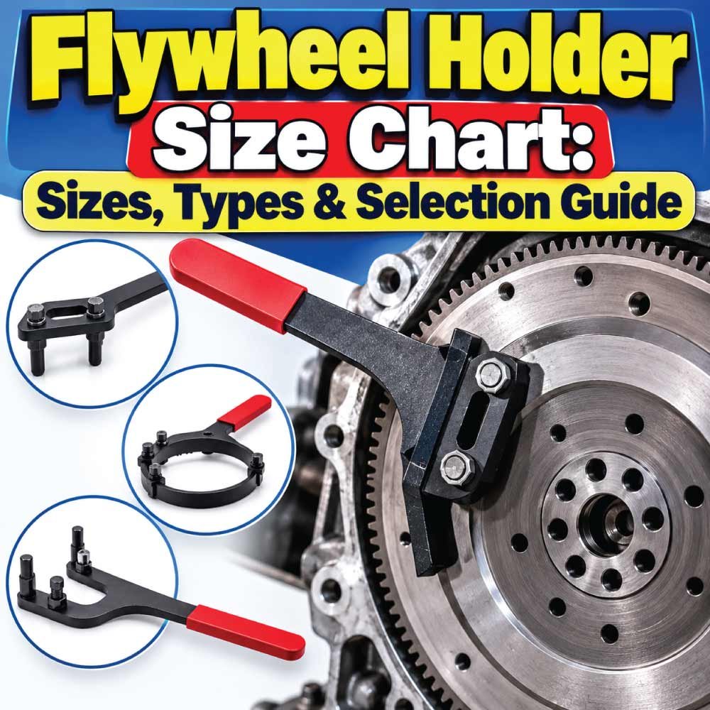
A flywheel holder is a workshop tool used to keep a flywheel, starter ring gear, clutch assembly, or related rotating component stationary while another fastener is loosened or tightened. Choosing the correct holder is important because the tool must engage the flywheel securely without damaging the teeth, rim, magnets, or other components.
Unlike bolts and sockets, flywheel holders do not follow one universal size system. Their dimensions and engagement methods vary according to the flywheel diameter, ring-gear tooth profile, available access, engine design, and tool type. Some holders use pins or jaws, while others grip the outer circumference or engage directly with the starter ring gear.
This Flywheel Holder Size Chart explains the main holder types, sizing factors, measurements, applications, compatibility considerations, and practical selection methods. It also covers common mistakes and answers frequently asked questions so you can identify the appropriate holder for a particular engine or mechanical job.
What Is a Flywheel Holder?
A flywheel holder is a mechanical holding tool designed to prevent a flywheel from rotating during service. It is particularly useful when working on a flywheel bolt, crankshaft fastener, clutch component, pulley, or other part that requires substantial torque.
Without a suitable holding method, the flywheel can rotate as torque is applied. Trying to stop it with an improvised object can damage the flywheel or create a safety hazard.
A proper holder generally works by one of several methods:
- Engaging flywheel or ring-gear teeth
- Gripping the outer circumference
- Using adjustable pins or jaws
- Locking into specific holes or slots
- Holding a particular flywheel shape or hub
The correct design depends heavily on the application.
Why Flywheel Holder Size Matters
The term “size” can refer to several different measurements rather than one standardized dimension.
Important sizing attributes include:
- Flywheel outside diameter
- Ring-gear diameter
- Tooth profile and spacing
- Thickness of the gripping area
- Jaw or pin opening
- Engagement depth
- Handle or tool length
- Mounting-hole spacing
- Shaft or hub dimensions
- Available clearance around the flywheel
A holder that physically reaches the flywheel may still be unsuitable if its engagement pattern does not match the component.
Flywheel Holder Size Chart
Because flywheel holders use different designs, there is no single universal numerical size chart. The following chart organizes holder selection by engagement method and application, rather than presenting unsupported universal dimensions.
| Holder Type | Primary Engagement | Sizing Requirement | Typical Application |
|---|---|---|---|
| Ring Gear Holder | Starter ring-gear teeth | Tooth form and access | Automotive engines |
| Universal Flywheel Holder | Adjustable jaws or pins | Flywheel diameter and gripping area | Multiple engine designs |
| Pin-Type Holder | Holes, slots, or openings | Pin diameter and spacing | Motorcycle and small engines |
| Jaw-Type Holder | Outer flywheel edge | Diameter and edge thickness | General workshop use |
| Strap-Style Holder | Outer circumference | Circumference and available clearance | Smooth or toothed flywheels |
| Dedicated Holder | Manufacturer-specific feature | Exact component compatibility | Specialized engines |
| Clutch/Flywheel Locking Tool | Flywheel or clutch structure | Engagement profile | Clutch service |
This chart should be treated as a selection framework, not a substitute for the manufacturer’s compatibility information. Exact dimensions differ significantly between tools.
Main Types of Flywheel Holders
Different flywheel designs require different holding methods. Understanding the tool type is often more important than simply looking for the largest or smallest holder.
Ring Gear Flywheel Holder
A ring-gear holder engages the teeth around the outer edge of the flywheel. The starter motor normally engages these teeth to crank the engine, and a suitable holding tool can use the same structure to resist rotation.
This type is particularly useful when:
- The flywheel has an accessible starter ring gear.
- The tool is designed for the specific tooth configuration.
- High resistance to rotation is required.
- There is enough clearance around the ring gear.
The key compatibility factors are tooth geometry, engagement depth, flywheel diameter, and access.
Universal Flywheel Holder
A universal flywheel holder is adjustable so that one tool can accommodate different flywheel configurations.
Depending on the design, adjustment may involve:
- Sliding pins
- Movable jaws
- Adjustable hooks
- Multiple engagement positions
- Replaceable contact points
Universal tools can be convenient for workshops that service several engine types. However, “universal” does not mean every flywheel will fit. The actual adjustment range and engagement design must still match the component.
Pin-Type Flywheel Holder
Pin-type holders use one or more pins to engage holes, slots, or other openings in the flywheel.
These tools are common where the flywheel provides dedicated engagement points.
Important measurements include:
- Pin diameter
- Pin-to-pin spacing
- Hole diameter
- Hole pattern
- Engagement depth
A pin that is too small may not provide secure engagement, while a pin that is too large may not enter the opening correctly.
Jaw-Type Flywheel Holder
Jaw-style tools grip the outside of the flywheel or a suitable section of its circumference.
Their fit depends primarily on the minimum and maximum gripping diameter and the thickness or geometry of the edge being held.
The jaws should contact a strong structural portion of the flywheel rather than a fragile cover, thin flange, sensor component, or magnet assembly.
Strap-Style Holder
A strap-style tool wraps around the outside of a rotating component and creates frictional resistance.
This design can be useful when the flywheel has a suitable smooth or accessible circumference. It may be less appropriate when the flywheel has delicate surfaces, sharp projections, or insufficient clearance.
How Flywheel Holder Sizes Are Determined
A flywheel holder should be selected according to the component it must hold, not merely according to the apparent physical size of the tool.
Measure Flywheel Outside Diameter
The outside diameter is one of the first measurements to establish.
Measure across the widest accessible portion of the flywheel using a suitable measuring instrument. Avoid measuring an attached component if the holder is intended to contact the flywheel itself.
For adjustable holders, compare this measurement with the manufacturer’s specified working range.
Measure Ring Gear Diameter
If the holder engages the starter ring gear, the ring-gear diameter can be important.
However, diameter alone does not establish compatibility. Two ring gears can have similar diameters while using different tooth configurations.
Therefore, record:
- Outside diameter
- Tooth arrangement
- Tooth thickness
- Available engagement area
- Distance from adjacent components
Measure Engagement Holes or Slots
For pin-type holders, carefully measure the relevant openings.
Record:
- Opening diameter or width
- Center-to-center spacing
- Number of openings
- Opening depth
- Relative position around the flywheel
A simple diameter measurement is not enough when the tool uses multiple pins.
Measure Edge Thickness
Jaw-type holders may need the thickness of the flywheel edge or ring being gripped.
A holder can have an adequate diameter range but still fail to grip correctly if the contact area is too thick, too thin, angled, or inaccessible.
Flywheel Holder Measurement Chart
The following chart provides a practical checklist for determining what should be measured before selecting a holder.
| Measurement | Why It Matters | Most Relevant Holder Type |
|---|---|---|
| Flywheel outside diameter | Determines physical working range | Jaw, universal |
| Ring-gear diameter | Helps establish tooth engagement area | Ring-gear holder |
| Tooth profile | Determines whether teeth can be engaged | Ring-gear holder |
| Tooth spacing | Prevents incompatible engagement | Ring-gear holder |
| Hole diameter | Determines pin compatibility | Pin holder |
| Hole spacing | Establishes pin arrangement | Pin holder |
| Edge thickness | Determines jaw fit | Jaw holder |
| Available clearance | Ensures the tool can be positioned | All types |
| Hub or mounting pattern | Helps identify component design | Dedicated holder |
| Engagement depth | Ensures secure contact | Pin and tooth holders |
Taking these measurements before purchasing a tool can prevent compatibility problems.
How to Choose the Correct Flywheel Holder
Selecting a holder is a process of matching the tool’s engagement system to the flywheel’s physical features.
Identify the Engine and Flywheel
Start with the engine or machine application. If the exact engine model is known, use that information when checking tool compatibility.
The engine identification may include:
- Manufacturer
- Model
- Engine family
- Production year
- Engine displacement
- Vehicle or machine application
Exact application information is often more useful than guessing from flywheel diameter.
Identify the Engagement Method
Look at the flywheel and determine what type of holder can safely engage it.
Ask:
- Does it have accessible ring-gear teeth?
- Are there holes for holding pins?
- Is the outer circumference suitable for gripping?
- Does it have a dedicated locking feature?
- Is there enough clearance for the tool?
This determines whether a tooth, pin, jaw, strap, or dedicated holder is appropriate.
Check the Working Range
For an adjustable holder, check its complete working range rather than assuming that a similar-looking tool will fit.
Important specifications can include:
- Minimum diameter
- Maximum diameter
- Pin range
- Jaw opening
- Tooth engagement capacity
- Handle clearance
The required measurement should fall comfortably within the specified operating range.
Check Tool Clearance
Clearance is frequently overlooked.
Even if a holder technically fits the flywheel, it may not work if nearby components prevent the tool from being installed.
Check the space around:
- Starter housings
- Bellhousings
- Engine blocks
- Clutch components
- Covers
- Wiring
- Sensors
- Mounting structures
A compact holder may be preferable when working in a restricted area.
Flywheel Holder Size Comparison by Application
Different applications place different demands on a holding tool.
| Application | Common Holder Approach | Important Fit Factors |
|---|---|---|
| Automotive flywheel service | Ring gear or dedicated holder | Tooth engagement and access |
| Manual transmission service | Flywheel/clutch holder | Flywheel design and clearance |
| Motorcycle service | Pin or adjustable holder | Hole pattern and pin diameter |
| Small engine service | Pin or universal holder | Flywheel openings and diameter |
| Industrial engine work | Heavy-duty dedicated holder | Engagement strength and clearance |
| Specialized engine service | Application-specific holder | Exact manufacturer compatibility |
These are general categories. The appropriate tool must still be matched to the actual flywheel.
Also Read:
Flywheel Holder vs. Flywheel Locking Tool
The terms flywheel holder and flywheel locking tool are sometimes used interchangeably, but they can describe different designs.
A flywheel holder generally provides temporary resistance against rotation. A locking tool may use a more specific engagement arrangement intended to positively prevent movement.
The distinction depends on the tool design.
A holder may use:
- Friction
- Jaws
- Pins
- Hooks
- Ring-gear engagement
A locking tool may use:
- Dedicated locking holes
- Fixed engagement teeth
- A transmission or engine mounting point
- Manufacturer-specific locking features
For high-torque operations, a positive mechanical engagement is generally preferable to relying only on friction.
Why a Flywheel Holder Is Used
The main purpose is to prevent unwanted rotation while another component is serviced.
Common uses include:
- Removing flywheel bolts
- Installing flywheel bolts
- Servicing clutch assemblies
- Holding crankshaft-related components
- Removing certain engine fasteners
- Maintaining flywheel position during inspection
- Supporting assembly procedures
A properly selected tool also helps reduce the temptation to use unsuitable methods such as wedging tools into gear teeth or placing excessive force on fragile components.
Advantages of Using the Correct Flywheel Holder
A purpose-designed holder provides several practical benefits.
Secure Mechanical Engagement
A properly matched tool can hold the flywheel without requiring an improvised locking method.
Better Access
Purpose-built holders are designed around common engine-service requirements and can provide access where ordinary gripping tools cannot.
Reduced Component Damage
Correct engagement distributes holding force through an appropriate structural area instead of concentrating force on a vulnerable component.
More Controlled Work
Keeping the flywheel stationary makes it easier to apply torque to the fastener being serviced.
Repeatable Workshop Procedure
A suitable holder can be used consistently during repeated maintenance operations, reducing reliance on improvised techniques.
Also Read:
Limitations and Compatibility Issues
No flywheel holder is suitable for every application.
Potential limitations include:
- Limited diameter range
- Incompatible tooth geometry
- Incorrect pin spacing
- Insufficient jaw opening
- Poor access
- Inadequate engagement depth
- Interference with surrounding components
- Insufficient holding capacity for the intended task
A universal tool may cover many applications but still be unsuitable for a particular flywheel.
For specialized engines, a dedicated tool may provide a more appropriate engagement pattern.
Common Mistakes When Selecting a Flywheel Holder
Several mistakes can lead to poor fit or component damage.
Choosing by Diameter Alone
A flywheel’s outside diameter does not tell you everything about holder compatibility.
The engagement design is equally important.
Ignoring Tooth Geometry
For ring-gear holders, matching the diameter without checking tooth configuration can result in poor engagement.
Using the Wrong Pin Size
Pin holders require compatible opening dimensions and spacing. A visually similar opening does not guarantee correct fit.
Ignoring Clearance
A tool may fit on paper but become unusable when installed because nearby components restrict movement.
Holding a Weak Surface
Do not assume that every part of the flywheel assembly is suitable for gripping. Thin covers, delicate components, and non-structural surfaces may not withstand holding force.
Assuming “Universal” Means Universal
Adjustable tools still have defined operating limits. Always compare the tool specifications with the actual flywheel.
Also Read:
How to Use a Flywheel Holder Safely
The correct installation procedure depends on the tool design, but several general practices apply.
- Turn off and secure the engine or machine.
- Ensure the flywheel and surrounding area are accessible.
- Identify a suitable structural engagement point.
- Position the holder according to its design.
- Make sure all pins, jaws, or teeth are fully engaged.
- Check that the holder does not contact vulnerable components.
- Apply force gradually rather than striking or shock-loading the holder.
- Keep hands away from potential pinch points.
- Remove the holder after the service operation is complete.
- Inspect the tool and flywheel for damage before reuse.
Always follow the tool manufacturer’s operating instructions and the applicable service procedure for the engine.
What Specifications Should You Check Before Buying?
A useful flywheel holder specification sheet may include several measurements and compatibility details.
Look for:
- Working diameter range
- Jaw opening
- Pin diameter
- Pin spacing
- Engagement profile
- Overall tool length
- Material and construction
- Handle design
- Application compatibility
- Weight
- Clearance requirements
Not every manufacturer publishes every measurement. When compatibility is uncertain, application-specific information should take priority over assumptions based on appearance.
Flywheel Holder Selection Checklist
Before selecting a tool, verify the following:
- Engine or machine model identified
- Flywheel type identified
- Engagement method determined
- Outside diameter measured where relevant
- Ring-gear characteristics checked where relevant
- Pin diameter measured where relevant
- Pin spacing measured where relevant
- Edge thickness checked for jaw holders
- Working range confirmed
- Surrounding clearance checked
- Tool application confirmed
- Manufacturer specifications reviewed
This checklist is especially useful when the flywheel is already removed and can be measured directly.
Frequently Asked Questions
What size flywheel holder do I need?
The required holder size depends on the flywheel design and engagement method, not just its diameter. Measure the relevant diameter, tooth arrangement, holes, spacing, edge thickness, and clearance, then compare those measurements with the tool’s specified range.
Are flywheel holders universal?
Some flywheel holders are adjustable and can work with multiple applications, but they are not universally compatible. Their working range and engagement method still have to match the flywheel.
Can a flywheel holder fit different flywheel diameters?
An adjustable holder may accommodate a range of diameters. However, the flywheel must also provide a suitable engagement point and enough clearance for the holder.
How do I measure a flywheel for a holder?
Measure the dimensions relevant to the holder design. For a jaw holder, this may include outside diameter and edge thickness. For a pin holder, measure hole diameter and spacing. For a ring-gear holder, examine tooth geometry and available engagement area.
Is a flywheel holder the same as a flywheel locking tool?
They can perform similar functions, but their designs may differ. A holder may grip or engage the flywheel temporarily, while a locking tool may use a dedicated positive locking feature.
Can I use a strap wrench instead of a flywheel holder?
A strap-style tool may work on an appropriate smooth, structurally strong circumference, but it is not automatically suitable for every flywheel. The holding method must be compatible with the component and the required service operation.
Why does my flywheel holder keep slipping?
Slipping can result from incorrect size, insufficient engagement, unsuitable contact surfaces, contamination, poor positioning, or a holder that is outside its intended working range. Recheck the tool’s compatibility rather than simply increasing force.
Should I choose a universal or dedicated holder?
A universal holder can be practical when servicing multiple compatible designs. A dedicated holder may be appropriate when the flywheel has a specific engagement pattern or when precise application compatibility is required.
Does flywheel diameter determine holder size?
Diameter is an important measurement for some holder designs, but it is not the only factor. Tooth geometry, pin spacing, edge thickness, engagement depth, and clearance can be equally important.
Can the wrong holder damage a flywheel?
Yes. Poor engagement can concentrate force on inappropriate surfaces, damage teeth or edges, bend components, or cause the tool to slip. Always use the intended engagement area and follow the applicable service procedure.
Final Flywheel Holder Selection Tips
A Flywheel Holder Size Chart is most useful when it is treated as a guide to the measurements and engagement features that actually determine compatibility. There is no single universal flywheel-holder dimension because holders are designed around different flywheel shapes and locking methods.
Before choosing a tool, identify the engine application, determine the flywheel engagement method, take the relevant measurements, and compare them with the holder’s published working range. For ring-gear tools, check tooth compatibility; for pin holders, verify hole diameter and spacing; and for jaw or strap holders, confirm the gripping diameter, edge geometry, and clearance.
The safest selection is one that provides secure mechanical engagement without contacting vulnerable components. When exact compatibility matters, use the applicable manufacturer documentation or service information rather than relying solely on a general size chart.

Engineer Hassan is a Mechanical Engineer with 16+ years of hands-on experience in mechanical hardware, fasteners, and workshop tools. He focuses on size selection, thread identification, and measurement, helping users choose the correct components with accuracy and safety.