
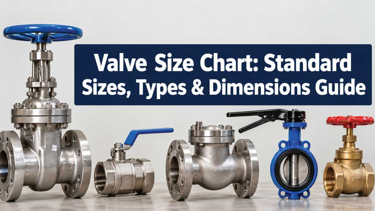
Choosing the correct valve size is essential for achieving proper flow, reliable shutoff, and compatibility with the piping system. A valve that is too small can restrict flow and increase pressure loss, while an incorrectly sized connection may not match the pipe or fitting.
A valve size chart helps you compare common nominal pipe sizes, DN designations, connection types, and valve dimensions. However, valve size is not simply the physical diameter of the valve opening. Nominal pipe size, outside diameter, inside diameter, pressure class, end connection, and manufacturer design all affect the actual dimensions.
This guide explains standard valve sizes, NPS and DN conversions, common valve types, important dimensions, measurement methods, and practical selection factors. It also explains why two valves with the same nominal size can have different body lengths, heights, weights, or flow characteristics.
What Is Valve Size?
Valve size normally refers to the nominal pipe size (NPS) or nominal diameter (DN) of the piping connection for which the valve is designed. It provides a standardized way to identify valves and compatible piping components.
For example, a valve marked NPS 2 is intended for a nominal 2-inch piping system. Its actual connection dimensions depend on the applicable pipe standard and valve end design.
In metric specifications, the equivalent designation may be expressed as DN 50. DN is a nominal designation rather than a direct measurement of the valve’s actual bore.
This distinction is important because nominal size does not always equal the measured internal or external diameter.
Nominal Size vs. Actual Dimensions
A valve can have several different dimensions that users may refer to as its “size”:
Nominal pipe size: The standardized pipe or connection designation.
Bore diameter: The internal opening through which fluid passes.
Outside diameter: The external diameter of a pipe or cylindrical connection.
Face-to-face length: Distance between the valve’s end faces.
Overall height: Distance from the valve connection plane to the highest point.
Flange dimensions: Bolt-circle diameter, flange thickness, and related dimensions.
Port size: Particularly important for ball, plug, and other internally ported valves.
Therefore, selecting a valve requires more than matching one number.
Valve Size Chart: NPS to DN Conversion
The following chart provides commonly used nominal size equivalents. These are nominal designations, not statements that the actual valve bore or outside diameter equals the number shown.
| NPS (in.) | DN (Nominal) | Common Description |
|---|---|---|
| 1/4 | DN 8 | Very small piping |
| 3/8 | DN 10 | Small piping |
| 1/2 | DN 15 | Small service lines |
| 3/4 | DN 20 | Small service lines |
| 1 | DN 25 | General small piping |
| 1-1/4 | DN 32 | Small-to-medium piping |
| 1-1/2 | DN 40 | Small-to-medium piping |
| 2 | DN 50 | Common process piping |
| 2-1/2 | DN 65 | Medium piping |
| 3 | DN 80 | Medium piping |
| 4 | DN 100 | Common industrial piping |
| 5 | DN 125 | Medium-to-large piping |
| 6 | DN 150 | Common industrial piping |
| 8 | DN 200 | Large piping |
| 10 | DN 250 | Large piping |
| 12 | DN 300 | Large piping |
| 14 | DN 350 | Large piping |
| 16 | DN 400 | Large piping |
| 18 | DN 450 | Large piping |
| 20 | DN 500 | Large piping |
| 24 | DN 600 | Very large piping |
The DN designation should be treated as a nominal reference. DN 50 and NPS 2 are commonly used as corresponding nominal designations, but they should not be interpreted as identical measured dimensions.
Common Valve Sizes
Valve sizes vary considerably by application. Small valves are frequently used for instrumentation, residential systems, laboratory equipment, and compact process lines. Larger valves are common in water distribution, power generation, chemical processing, oil and gas, and industrial utilities.
Small Valve Sizes
Typical small valve sizes include:
- 1/4 inch
- 3/8 inch
- 1/2 inch
- 3/4 inch
- 1 inch
- 1-1/4 inch
- 1-1/2 inch
Small valves are often available with threaded, compression, socket, or other compact connection arrangements.
Medium Valve Sizes
Common medium sizes include:
- 2 inch
- 2-1/2 inch
- 3 inch
- 4 inch
- 5 inch
- 6 inch
- 8 inch
These sizes are widely encountered in commercial and industrial piping systems.
Large Valve Sizes
Larger systems may use:
- 10 inch
- 12 inch
- 14 inch
- 16 inch
- 18 inch
- 20 inch
- 24 inch
- Larger custom or engineered sizes
Large valves can have substantial body weight and installation requirements. Their dimensions should be checked from the manufacturer’s dimensional drawing before installation.
Valve Types and How Size Affects Them
Different valve designs use the same nominal pipe sizes but have different construction, flow paths, operating mechanisms, and dimensional requirements.
Ball Valve Sizes
Ball valves use a rotating ball with a passage through it to control flow. They are available in many nominal pipe sizes, from small threaded valves to large industrial flanged designs.
A ball valve’s actual flow capacity depends on factors such as:
- Port configuration
- Bore diameter
- Pressure rating
- Fluid properties
- Valve design
- Connection size
A full-port ball valve generally provides a larger flow passage than a reduced-port design of the same nominal connection size.
Gate Valve Sizes
Gate valves use a moving gate to start or stop flow. They are commonly used where the valve is intended primarily for isolation rather than frequent throttling.
Gate valves can be supplied in threaded, socket, flanged, and other configurations. Their face-to-face and overall dimensions vary according to design and applicable standards.
Globe Valve Sizes
Globe valves use a movable closure element and are commonly associated with flow regulation or throttling applications.
Because the internal flow path differs from a straight-through ball or gate valve, a globe valve can have different flow characteristics even when its nominal connection size is identical.
Butterfly Valve Sizes
Butterfly valves use a rotating disc positioned within the flow passage. They are particularly common in larger-diameter piping because the design can be relatively compact compared with some other valve types.
Common configurations include:
- Wafer
- Lug
- Flanged
- Double-flanged
The outside diameter, disc clearance, flange compatibility, and actuator dimensions should be checked before installation.
Check Valve Sizes
Check valves automatically help prevent reverse flow. Common designs include swing, lift, wafer, dual-plate, and other configurations.
A check valve’s size should match the piping connection, but its flow direction, pressure rating, installation orientation, and minimum flow requirements may also matter.
Valve Dimensions You Need to Check
A valve size chart can identify nominal size, but installation often requires several additional dimensions.
Face-to-Face Dimension
The face-to-face dimension is the distance between the valve’s connection faces. It is particularly important when replacing an existing valve.
A replacement valve with the correct NPS but a different face-to-face length may not fit the existing pipe arrangement without modification.
Overall Height
Overall height becomes important when valves are installed in:
- Mechanical rooms
- Pipe racks
- Equipment skids
- Underground chambers
- Enclosures
- Areas with limited overhead clearance
For actuated valves, include the actuator and any accessories when evaluating installation clearance.
Connection Dimensions
Flanged valves require more than a nominal size match. Relevant dimensions can include:
- Flange outside diameter
- Bolt-hole arrangement
- Bolt-circle diameter
- Number of bolt holes
- Flange thickness
- Facing details
These dimensions depend on the applicable flange standard and pressure class.
Valve Pressure Class and Size
Valve size and pressure rating are separate specifications. A 2-inch valve, for example, does not automatically have one universal pressure rating.
The pressure capability can depend on:
- Valve material
- Valve design
- Temperature
- Pressure class
- End connection
- Applicable standard
- Manufacturer’s design
Common industrial flange pressure-class designations may include Class 150, 300, 600, 900, 1500, and 2500, but these should not be treated as interchangeable with every valve or piping system.
A valve selected for a high-pressure service must be checked against the appropriate pressure-temperature rating rather than selected from size alone.
How to Measure Valve Size
If the valve marking is unavailable or unclear, physical measurement can help identify the nominal connection size. However, measurement alone may not establish the complete valve specification.
Step 1: Identify the Connection Type
First determine whether the valve is:
- Threaded
- Flanged
- Socket-weld
- Butt-weld
- Wafer
- Lug
- Compression or another specialized connection
The connection type determines which dimensions should be measured.
Step 2: Check Existing Markings
Look for markings on the valve body, nameplate, tag, or handle area.
Useful markings may include:
- NPS
- DN
- Pressure class
- Material designation
- Manufacturer identification
- Model or part number
- Flow-direction arrow
A readable manufacturer’s identification is often more useful than estimating nominal size from a single physical measurement.
Step 3: Measure the Relevant Diameter
For a threaded connection, measure the appropriate outside diameter and identify the thread standard and pitch. Do not assume that the measured diameter will equal the nominal valve size.
For flanged valves, measure the flange and bolt pattern as well as the pipe connection.
Step 4: Measure Face-to-Face Length
Measure from one connection face to the corresponding opposite face. Keep the valve aligned and use the appropriate reference points.
This measurement is particularly useful when determining whether a replacement valve can occupy the same space.
Step 5: Verify the Specification
Compare the measurements with the manufacturer’s dimensional information or the applicable standard.
This final step is important because two valves can have the same nominal size while differing in:
- Body dimensions
- Face-to-face length
- Port diameter
- Pressure rating
- End connection
- Actuator arrangement
Also Read:
How to Choose the Correct Valve Size
Correct valve selection combines pipe compatibility with flow and service requirements.
Match the Nominal Pipe Size
Start by identifying the pipe’s nominal size and the required valve connection. The valve should be compatible with the pipe, fittings, and joining method.
Do not select a valve simply because its measured outside diameter appears similar to the pipe.
Consider Required Flow
Valve sizing may depend on the required flow rate and allowable pressure drop. A valve that is physically compatible with the pipe may not provide the desired flow performance.
For control applications, additional engineering parameters may be required, including the valve’s flow coefficient and operating conditions.
Check Pressure and Temperature
Confirm that the valve is suitable for the system’s maximum pressure and operating temperature.
Pressure-temperature ratings can change with material and valve construction, so the manufacturer’s rating should be checked for the actual service conditions.
Consider the Fluid
The medium being controlled can affect valve selection. Water, air, steam, chemicals, oils, gases, and abrasive fluids may require different materials or valve designs.
Important considerations include:
- Corrosion resistance
- Temperature
- Viscosity
- Cleanliness
- Chemical compatibility
- Presence of solids
- Gas or liquid service
Check the Installation Space
Before ordering a valve, verify available clearance around the body, handwheel, lever, actuator, and maintenance areas.
A valve that fits the pipe can still be unsuitable if its operating mechanism cannot be accessed.
Also Read:
Valve Size by Connection Type
The same nominal valve size can have different installation requirements depending on its connection.
| Connection Type | Typical Use | Important Dimension Considerations |
|---|---|---|
| Threaded | Small piping | Thread size, pitch, connection length |
| Flanged | Industrial piping | Bolt pattern, flange dimensions, facing |
| Wafer | Compact installations | Flange compatibility, body thickness |
| Lug | Piping requiring bolted retention | Lug pattern and flange alignment |
| Butt-weld | Permanent industrial piping | Pipe OD, wall thickness, weld preparation |
| Socket-weld | Smaller industrial piping | Socket dimensions and pipe compatibility |
| Compression | Tubing and compact systems | Tube OD and fitting configuration |
Connection compatibility should always be checked independently from nominal size.
Valve Size and Pipe Size Are Not Always the Same
One of the most common mistakes is assuming that a valve must have exactly the same internal opening as the pipe.
A piping system may use a valve with a nominal size corresponding to the pipe while the valve has a reduced internal port. Conversely, specialized designs may provide flow passages that differ significantly from a simple nominal-diameter assumption.
Reducers, expanders, bushings, and other fittings can also connect components of different nominal sizes.
For example, a piping arrangement may intentionally transition from a larger pipe to a smaller valve. Whether that arrangement is appropriate depends on the application and engineering requirements.
Valve Size Chart for Quick Selection
The following chart is useful as a starting reference for common nominal sizes.
| Nominal Size | DN Designation | Typical Piping Category | Common Valve Types |
|---|---|---|---|
| 1/2 in. | DN 15 | Small | Ball, globe, check |
| 3/4 in. | DN 20 | Small | Ball, globe, check |
| 1 in. | DN 25 | Small | Ball, gate, globe |
| 1-1/2 in. | DN 40 | Small/medium | Ball, gate, check |
| 2 in. | DN 50 | Medium | Ball, gate, globe, check |
| 3 in. | DN 80 | Medium | Butterfly, gate, ball |
| 4 in. | DN 100 | Medium | Butterfly, gate, globe |
| 6 in. | DN 150 | Large | Butterfly, gate, check |
| 8 in. | DN 200 | Large | Butterfly, gate, check |
| 10 in. | DN 250 | Large | Butterfly, gate, ball |
| 12 in. | DN 300 | Large | Butterfly, gate, check |
| 16 in. | DN 400 | Very large | Butterfly, gate, specialty valves |
| 20 in. | DN 500 | Very large | Butterfly, gate, specialty valves |
| 24 in. | DN 600 | Very large | Butterfly, gate, specialty valves |
This is a nominal size reference, not a dimensional drawing. Actual body and connection dimensions should be verified for the specific valve.
Also Read:
Common Valve Sizing Mistakes
Incorrect valve selection often comes from treating nominal size as the only specification.
Mistake 1: Measuring Only the Bore
The internal opening can help identify the design, but it does not necessarily identify the nominal pipe size.
Mistake 2: Ignoring the Connection Standard
A valve can have the correct nominal size but the wrong thread, flange, weld connection, or facing configuration.
Mistake 3: Choosing by Pipe Size Alone
Pipe compatibility is necessary, but flow rate, pressure, temperature, fluid characteristics, and valve function may require additional sizing.
Mistake 4: Forgetting Face-to-Face Length
This is especially problematic when replacing an installed flanged valve.
Mistake 5: Ignoring Actuator Clearance
An actuated valve requires enough room for operation, maintenance, removal, and accessory installation.
Mistake 6: Assuming All Valves of One Size Are Identical
Valve dimensions vary by type, pressure class, material, manufacturer, connection, and applicable standard.
Valve Size Selection Checklist
Before purchasing or installing a valve, verify the following:
Nominal pipe size
NPS or DN designation
Valve type
End connection
Pressure rating
Operating temperature
Fluid or medium
Required flow rate
Flow direction
Face-to-face dimension
Overall height and width
Material compatibility
Actuator or handle clearance
Applicable dimensional standard
Manufacturer’s model and specification
For replacement work, compare the new valve’s dimensional drawing with the existing installation rather than relying on nominal size alone.
Frequently Asked Questions About Valve Sizes
Is valve size the same as pipe size?
Usually, the valve is specified for a nominal pipe size, but valve size should not be interpreted as its exact internal or external diameter. A valve’s bore and body dimensions can differ from the nominal designation.
What does NPS mean on a valve?
NPS means Nominal Pipe Size. It is a standardized designation used primarily with inch-based piping systems. The NPS number is nominal and does not always equal the measured pipe diameter.
What does DN mean on a valve?
DN means nominal diameter. It is commonly used in metric-oriented piping specifications. DN provides a standardized nominal reference rather than a guarantee of a specific measured bore.
What is DN 50 valve size?
DN 50 is commonly used as the nominal equivalent designation for NPS 2. The actual valve dimensions depend on the valve type, connection configuration, applicable standard, and manufacturer.
How do I know what size valve I need?
Start with the pipe’s nominal size and connection type, then consider flow requirements, pressure, temperature, fluid compatibility, valve function, installation space, and applicable specifications.
Can a smaller valve be used on a larger pipe?
A smaller valve can be incorporated into a larger piping system using an appropriate transition arrangement, but this should not be done simply to reduce cost or size. The effect on flow, pressure loss, velocity, and system performance must be considered.
Does valve size determine flow rate?
Valve size influences flow capacity, but it does not determine flow rate by itself. Valve design, port size, pressure differential, fluid properties, and flow coefficient also affect actual performance.
Conclusion
A valve size chart is a useful starting point for identifying nominal pipe sizes, comparing NPS and DN designations, and understanding common valve options. However, nominal size is only one part of correct valve selection.
For a reliable match, verify the valve type, nominal size, connection, pressure-temperature rating, flow requirements, material, face-to-face dimensions, and available installation clearance. When replacing an existing valve, physical dimensions and connection details are especially important.
The most reliable approach is to use the size chart for initial identification and then confirm the exact dimensions and ratings against the specific valve’s technical documentation and applicable piping requirements.

Engineer Hassan is a Mechanical Engineer with 16+ years of hands-on experience in mechanical hardware, fasteners, and workshop tools. He focuses on size selection, thread identification, and measurement, helping users choose the correct components with accuracy and safety.