
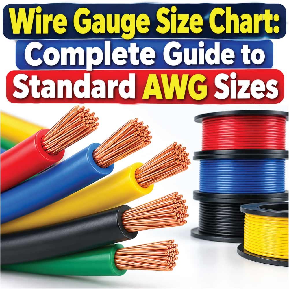
Choosing the right wire size is easier when you understand how American Wire Gauge (AWG) works. Wire gauge describes the conductor size, and the gauge number is directly related to the wire’s diameter and cross-sectional area. One important detail is that a smaller AWG number means a larger conductor. For example, 12 AWG is larger than 14 AWG, while 4 AWG is much larger than 10 AWG.
A reliable wire gauge size chart helps you compare common wire sizes by diameter, area, and other electrical characteristics. However, selecting a wire should not be based on gauge alone. Conductor material, insulation, installation conditions, temperature, circuit length, and allowable ampacity can all affect the appropriate choice.
This guide explains AWG sizes, how to read a wire gauge chart, common wire dimensions, resistance, ampacity considerations, and practical ways to identify or measure an unknown wire.
What Is Wire Gauge?
Wire gauge is a standardized way of describing the diameter of electrical conductors. In North America, the American Wire Gauge (AWG) system is widely used for copper and aluminum electrical wire and cable.
AWG numbers follow a reverse relationship with conductor size:
- Lower gauge number = larger conductor
- Higher gauge number = smaller conductor
- Larger conductors generally have lower electrical resistance
- Smaller conductors generally have higher resistance
AWG is a logarithmic sizing system rather than a simple linear scale. This means the difference between consecutive gauge sizes follows a predictable geometric relationship.
For example, 10 AWG has a larger diameter than 12 AWG, and 12 AWG is larger than 14 AWG. The difference is not simply a fixed number of millimeters or inches.
The AWG designation normally describes the conductor itself, not the complete outside diameter of an insulated cable. Insulation thickness can vary considerably between cable types and applications.
How Does the AWG System Work?
The AWG system is based primarily on conductor diameter. As the AWG number increases, the conductor diameter decreases.
The relationship is especially useful when comparing wires that appear similar. A small change in gauge can represent a meaningful difference in cross-sectional area and electrical resistance.
AWG is commonly used for:
- Building wire
- Appliance wiring
- Automotive wiring
- Control wiring
- Electronic wiring
- Battery cables
- Flexible cords
- Grounding conductors
- Electrical equipment wiring
Larger conductors may also be identified using kcmil, especially for large power conductors. Kcmil refers to thousands of circular mils and is commonly encountered with conductors larger than the ordinary AWG range.
Wire Gauge Size Chart
The following chart provides commonly used AWG conductor dimensions. Diameter and area values are nominal conductor dimensions; actual manufactured products can vary by construction and tolerance.
| AWG | Diameter (in) | Diameter (mm) | Area (mm²) | Area (kcmil) |
|---|---|---|---|---|
| 4 | 0.2043 | 5.189 | 21.15 | 41.74 |
| 6 | 0.1620 | 4.115 | 13.30 | 26.24 |
| 8 | 0.1285 | 3.264 | 8.367 | 16.51 |
| 10 | 0.1019 | 2.588 | 5.261 | 10.38 |
| 12 | 0.0808 | 2.053 | 3.309 | 6.530 |
| 14 | 0.0641 | 1.628 | 2.081 | 4.107 |
| 16 | 0.0508 | 1.291 | 1.309 | 2.583 |
| 18 | 0.0403 | 1.024 | 0.823 | 1.624 |
| 20 | 0.0320 | 0.812 | 0.518 | 1.022 |
| 22 | 0.0253 | 0.644 | 0.326 | 0.644 |
| 24 | 0.0201 | 0.511 | 0.205 | 0.511 |
| 26 | 0.0159 | 0.405 | 0.129 | 0.404 |
| 28 | 0.0126 | 0.321 | 0.0810 | 0.321 |
| 30 | 0.0100 | 0.255 | 0.0509 | 0.101 |
These dimensions describe the conductor rather than the complete insulated wire. Manufacturer specifications can also list complete conductor diameter, insulation diameter, weight, resistance, and other properties. For example, manufacturer data for copper conductors provides conductor diameter and circular-mil area alongside electrical characteristics.
Understanding Wire Diameter and Cross-Sectional Area
Diameter is one of the easiest ways to visualize wire gauge, but cross-sectional area is equally important.
A larger conductor has more conductive material available for carrying current. This generally means lower resistance for the same conductor material and length.
For a round solid conductor, cross-sectional area is related to diameter by:
A = πd² / 4
where:
- A = cross-sectional area
- d = conductor diameter
- π = approximately 3.1416
Because area depends on the square of diameter, a relatively small change in diameter can produce a larger change in cross-sectional area.
This is one reason you should not judge wire capacity simply by looking at its diameter.
Why Cross-Sectional Area Matters
Cross-sectional area helps describe how much conductive material exists in the wire. It is particularly useful when comparing AWG with metric conductor sizes.
For example, 12 AWG has a nominal area of approximately 3.31 mm², while 14 AWG has approximately 2.08 mm².
The two sizes may look relatively close, but they do not have the same electrical characteristics.
Common AWG Wire Sizes and Their Uses
Different wire gauges are commonly encountered in different types of electrical work. The exact application depends on the conductor material, insulation, installation method, temperature rating, and applicable electrical requirements.
12 AWG Wire
12 AWG is a common electrical conductor size used in many residential and general-purpose wiring applications. Its nominal conductor diameter is about 2.05 mm, with a cross-sectional area of approximately 3.31 mm².
The appropriate current-carrying capacity depends on the complete wiring system and applicable code requirements rather than gauge alone.
14 AWG Wire
14 AWG has a nominal diameter of approximately 1.63 mm and an area of about 2.08 mm².
It is frequently encountered in smaller branch-circuit wiring and electrical equipment, subject to the requirements of the specific installation.
10 AWG Wire
10 AWG is larger than both 12 AWG and 14 AWG. Its nominal diameter is approximately 2.59 mm, with an area of about 5.26 mm².
It is commonly encountered where a circuit requires a larger conductor than typical 12 or 14 AWG wiring.
8 AWG and Larger
8 AWG, 6 AWG, and 4 AWG are substantially larger conductors. These sizes may be used for feeders, equipment connections, battery systems, larger electrical loads, and other applications requiring larger conductors.
The correct application depends on the equipment and installation requirements.
Wire Gauge vs Ampacity
One of the most common mistakes is assuming that every wire of a particular gauge has one universal ampacity.
It does not.
Ampacity is the maximum current a conductor can carry under specified conditions without exceeding its permitted temperature rating. The allowable value can depend on factors such as:
- Conductor material
- Insulation temperature rating
- Ambient temperature
- Number of current-carrying conductors
- Installation method
- Raceway or cable configuration
- Terminal temperature limitations
- Applicable electrical code
For example, manufacturer data can provide an ampacity for a particular conductor under specific stated conditions. Southwire’s published conductor specifications show that ampacity is associated with defined conditions rather than being an isolated property of the AWG number.
Therefore, a wire gauge chart should be used as a sizing reference, not as a substitute for the applicable electrical code or manufacturer specifications.
How Wire Gauge Affects Electrical Resistance
Wire resistance is another important reason conductor size matters.
For the same conductor material and length, a larger cross-sectional area generally produces lower resistance. A smaller conductor has less conductive material and therefore generally has higher resistance.
Resistance can be expressed using:
R = ρL / A
where:
- R = resistance
- ρ = resistivity of the conductor material
- L = conductor length
- A = cross-sectional area
This relationship also explains why cable length matters.
A short piece of wire and a very long piece of the same AWG wire have the same nominal conductor size, but the longer conductor has greater total resistance.
Temperature also affects conductor resistance. Manufacturer specifications commonly state resistance at a defined temperature, such as 20°C or 25°C, so resistance figures should always be interpreted alongside their test conditions.
How to Read a Wire Gauge Chart
A wire gauge chart may contain much more information than just AWG number and diameter.
When reading one, look for these columns:
| Chart Term | What It Means |
|---|---|
| AWG | American Wire Gauge designation |
| Diameter | Nominal conductor diameter |
| Area | Cross-sectional conductor area |
| Circular mils | Area expressed using circular-mil units |
| Resistance | Electrical resistance for a specified length and temperature |
| Ampacity | Allowable current under specified conditions |
| Weight | Conductor or cable weight for a stated length |
Not every chart uses the same units or test conditions.
A manufacturer may also distinguish between solid and stranded conductors. For example, Southwire publishes separate information for solid and stranded bare copper conductors, including conductor dimensions and resistance.
Also Read:
Solid Wire vs Stranded Wire
AWG can describe both solid and stranded conductors, but their physical construction is different.
Solid wire consists of one continuous conductor. It is relatively rigid and is often used where the wire will remain stationary.
Stranded wire consists of multiple smaller wires grouped together. It is generally more flexible and is useful where movement, vibration, or repeated bending is expected.
Two conductors carrying the same AWG designation can therefore look different.
A stranded conductor’s overall diameter may also be different from the diameter of an equivalent solid conductor because the individual strands do not occupy the entire geometric space without gaps.
When selecting connectors, terminals, lugs, or fittings, always check whether the component is designed for the particular conductor construction.
Copper Wire Gauge vs Aluminum Wire Gauge
AWG describes physical conductor size, but conductor material also matters.
Copper and aluminum have different electrical and mechanical characteristics. A copper conductor and an aluminum conductor with the same nominal AWG designation should not automatically be assumed to have identical performance in every application.
When working with aluminum conductors, pay attention to:
- The conductor material specified by the manufacturer
- Terminal compatibility
- Temperature ratings
- Installation requirements
- Applicable electrical codes
- Approved connectors and terminations
The conductor material should therefore be considered alongside the gauge.
How to Measure an Unknown Wire Gauge
If the wire marking is unreadable, you can estimate its gauge by measuring the conductor.
Measure the Conductor Diameter
First, remove insulation carefully from a small section if necessary and measure the actual conductor—not the outside of the insulation.
A digital caliper can provide a useful diameter measurement.
Then compare the measured diameter with an AWG chart.
For example, a conductor measuring close to 2.05 mm in diameter is approximately the nominal diameter associated with 12 AWG.
However, stranded wire requires extra care because the overall bundle diameter is not necessarily equivalent to the diameter of a solid conductor.
Check the Wire Marking
Before measuring, inspect the cable jacket or insulation. Many manufactured wires and cables have markings that identify:
- AWG size
- Conductor material
- Voltage rating
- Temperature rating
- Manufacturer
- Cable type
- Number of conductors
If the marking is available and readable, it is generally more reliable than estimating the gauge visually.
Also Read:
AWG and Metric Wire Sizes
AWG is primarily used in North America, while many countries use metric conductor sizes expressed in square millimeters.
The two systems do not always correspond to exact one-to-one equivalents.
For example:
| AWG | Approx. Area (mm²) | Approx. Diameter (mm) |
|---|---|---|
| 14 | 2.08 | 1.628 |
| 12 | 3.31 | 2.053 |
| 10 | 5.26 | 2.588 |
| 8 | 8.37 | 3.264 |
| 6 | 13.30 | 4.115 |
| 4 | 21.15 | 5.189 |
When converting between systems, do not simply assume that the nearest metric number is automatically an approved substitute. The electrical design, equipment terminals, applicable standards, and installation requirements still need to be considered.
Factors to Consider When Choosing Wire Size
The correct wire gauge depends on more than the current flowing through the circuit.
Consider the following factors before selecting a conductor:
- Current: Determine the expected load current.
- Circuit length: Longer circuits can experience greater voltage drop.
- Conductor material: Copper and aluminum behave differently.
- Insulation: Temperature and insulation type affect allowable use.
- Installation method: Raceway, cable, free air, and other installations can have different requirements.
- Ambient temperature: Higher surrounding temperatures can affect allowable ampacity.
- Number of conductors: Grouping can influence allowable current.
- Voltage: Lower-voltage systems can be particularly sensitive to voltage drop.
- Equipment terminals: Termination ratings must be compatible with the conductor.
- Local requirements: Follow the electrical code and standards applicable to the installation.
This is why a wire gauge size chart is best viewed as one part of the sizing process.
Also Read:
Wire Gauge and Voltage Drop
Voltage drop occurs when electrical resistance in a circuit causes the voltage available at the load to be lower than the source voltage.
Wire size, conductor material, current, and circuit length all influence voltage drop.
A longer cable run generally creates more resistance than a shorter run of the same wire size. Increasing conductor size reduces resistance and can reduce voltage drop.
For this reason, a conductor that appears adequate based only on current may require further evaluation when the circuit is unusually long.
Voltage-drop calculations should use the actual circuit conditions rather than relying only on a generic AWG chart.
Common Mistakes When Using an AWG Chart
Using an AWG chart is straightforward, but several mistakes can lead to incorrect wire selection.
Assuming a Higher Number Means a Larger Wire
AWG works in reverse.
10 AWG is larger than 14 AWG, not smaller.
This is one of the first rules to remember when reading an American Wire Gauge chart.
Measuring the Insulated Cable
The insulation is not part of the AWG conductor measurement.
If you measure the complete outside diameter of an insulated cable, the result can be much larger than the actual conductor diameter.
Using Gauge Alone to Determine Ampacity
AWG does not provide one universal ampacity for every possible installation.
Temperature, insulation, conductor material, installation conditions, and electrical requirements all matter.
Ignoring Cable Length
A conductor’s resistance increases with length. Long runs therefore require additional voltage-drop consideration.
AWG Size Chart vs Cable Size Chart
The terms wire size and cable size are sometimes used interchangeably, but they are not always describing exactly the same thing.
AWG generally identifies the conductor size.
A cable specification may include:
- Number of conductors
- Conductor AWG
- Stranding
- Insulation thickness
- Jacket thickness
- Overall cable diameter
- Voltage rating
- Temperature rating
- Shielding
- Weight
For example, a manufacturer’s medium-voltage cable specification can list conductor diameter separately from diameter over insulation and overall cable dimensions.
Therefore, when physical installation space matters, look beyond the AWG number and check the manufacturer’s complete cable dimensions.
Final Thoughts on Wire Gauge Sizes
A wire gauge size chart provides a convenient way to compare AWG numbers, conductor diameters, and cross-sectional areas. The most important rule is simple: the smaller the AWG number, the larger the conductor.
However, choosing the correct wire requires more than matching a current value to a gauge. Conductor material, insulation, circuit length, installation conditions, temperature, voltage drop, terminals, and applicable electrical requirements should all be considered.
For identifying an unknown wire, start with the cable markings whenever possible. If markings are unavailable, measure the actual conductor carefully and compare the result with a reliable AWG reference.
For final installation decisions, use the applicable electrical code and the manufacturer’s specifications for the exact wire or cable being installed. Manufacturer data demonstrates why conductor dimensions, resistance, ampacity, and construction should be evaluated together rather than treating AWG as the only specification.

Engineer Hassan is a Mechanical Engineer with 16+ years of hands-on experience in mechanical hardware, fasteners, and workshop tools. He focuses on size selection, thread identification, and measurement, helping users choose the correct components with accuracy and safety.