
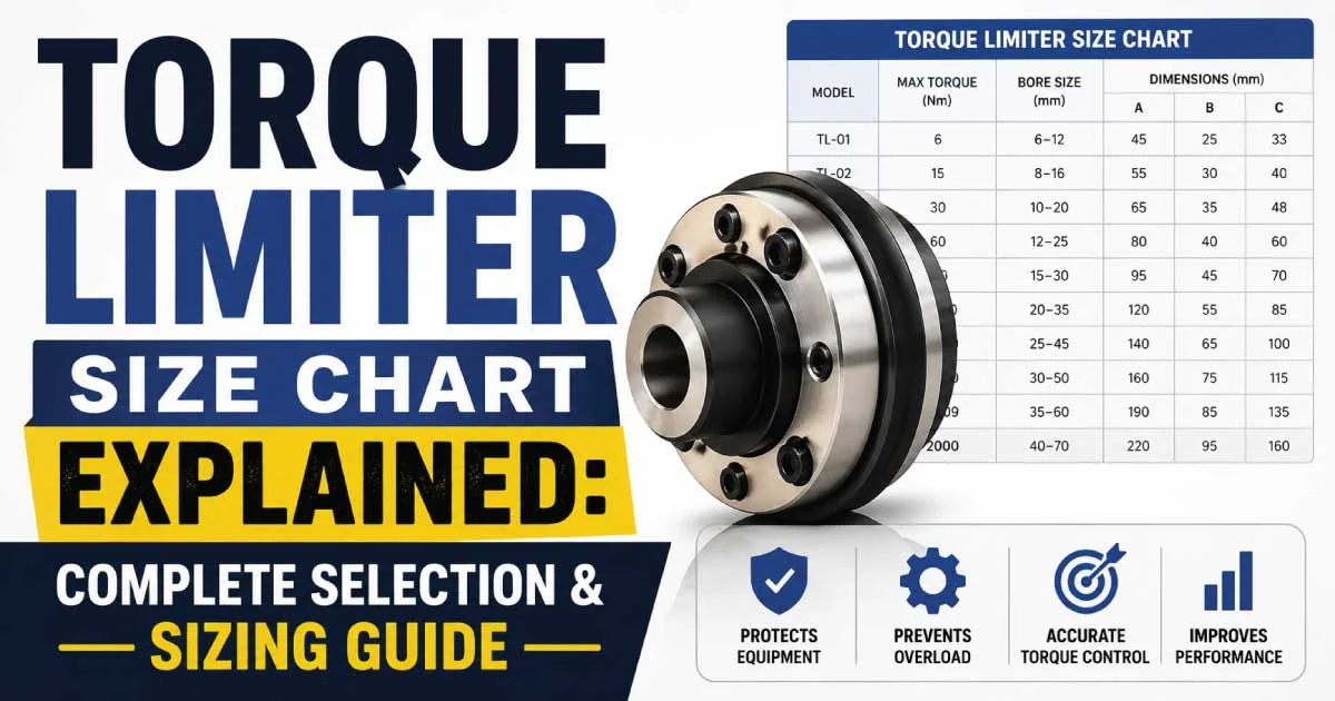
Torque limiters are essential mechanical safety devices designed to protect machinery from overload damage. Selecting the correct size is critical for achieving reliable performance, longer equipment life, and reduced maintenance costs.
This complete guide explains torque limiter size charts, sizing principles, and the key factors every engineer, technician, or machine designer should understand before choosing the right torque limiter.
What Is a Torque Limiter?
A torque limiter is a mechanical power transmission device that disconnects or limits torque when it exceeds a predetermined value. Instead of allowing excessive force to damage expensive equipment, the limiter slips, disengages, or releases the drive until the overload condition is removed, ensuring the machine remains protected during unexpected operating conditions.
Why Torque Limiter Size Matters
Selecting the proper torque limiter size directly affects equipment reliability and operational safety. An undersized limiter may disengage unnecessarily during normal operation, while an oversized model could fail to protect machinery from overload. Correct sizing ensures smooth power transmission, minimizes downtime, and extends the lifespan of gears, shafts, bearings, and motors.
Understanding a Torque Limiter Size Chart
A torque limiter size chart is a reference table that matches torque capacity, bore diameter, shaft size, and operating specifications.
Manufacturers use these charts to help users identify the correct limiter based on machine requirements, ensuring compatibility with the drive system while maintaining optimal overload protection.
Main Components of a Torque Limiter Size Chart
Most manufacturers include several important specifications within a torque limiter size chart. Understanding each parameter makes selecting the right limiter much easier.
- Torque range (Nm or lb-ft)
- Maximum bore diameter
- Outside diameter
- Overall length
- Hub dimensions
- Weight
- Maximum rotational speed
- Mounting configuration
- Material specifications
These measurements ensure compatibility with existing machine components.
How Torque Is Measured
Torque represents the rotational force applied to a shaft or mechanical component. It is commonly measured in:
- Newton-meters (Nm)
- Pound-feet (lb-ft)
- Pound-inches (lb-in)
Industrial equipment manufacturers generally specify required operating torque in the machine manual, making it easier to compare with the torque limiter size chart before installation.
Factors That Influence Torque Limiter Size Selection
Several operating conditions determine which torque limiter size should be selected. Ignoring any of these factors may result in poor performance or premature equipment failure.
- Motor power
- Operating speed (RPM)
- Maximum transmitted torque
- Shock load frequency
- Shaft diameter
- Duty cycle
- Environmental conditions
- Mounting style
Each factor contributes to determining the ideal limiter capacity.
Relationship Between Shaft Diameter and Torque Capacity
Larger shafts generally transmit greater torque, requiring larger torque limiters with higher load capacities. A size chart correlates shaft bore dimensions with allowable torque ratings, ensuring the selected limiter fits securely without compromising safety or mechanical efficiency during operation.
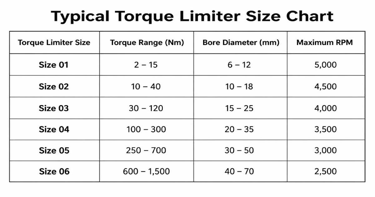
Typical Torque Limiter Size Chart Example
Below is a simplified example of a commonly used torque limiter sizing chart.
| Torque Limiter Size | Torque Range (Nm) | Bore Diameter (mm) | Maximum RPM |
|---|---|---|---|
| Size 01 | 2 – 15 | 6 – 12 | 5,000 |
| Size 02 | 10 – 40 | 10 – 18 | 4,500 |
| Size 03 | 30 – 120 | 15 – 25 | 4,000 |
| Size 04 | 100 – 300 | 20 – 35 | 3,500 |
| Size 05 | 250 – 700 | 30 – 50 | 3,000 |
| Size 06 | 600 – 1,500 | 40 – 70 | 2,500 |
Torque Limiter Size Chart PDF
A torque limiter size chart helps you choose the correct torque limiter based on torque capacity, bore diameter, and maximum operating speed. Selecting the right size protects machinery from overload, improves performance, and extends equipment life. Use this chart as a quick reference for identifying the most suitable torque limiter for your application.
Note: Actual dimensions vary between manufacturers.
How to Read a Torque Limiter Size Chart
Reading a torque limiter size chart involves matching your machine’s operating torque with the appropriate size while ensuring the bore diameter fits the shaft. Verify the maximum speed rating, mounting style, and dimensional compatibility before finalizing the selection to achieve reliable overload protection and efficient machine performance.
Common Types of Torque Limiters
Different torque limiters are designed for different industrial applications. Choosing the appropriate type is just as important as selecting the correct size.
Friction Torque Limiters
Friction torque limiters use friction plates to slip during overload conditions. They automatically resume transmitting torque once the overload is removed, making them ideal for conveyors, packaging equipment, and general industrial machinery requiring continuous operation.
Ball Detent Torque Limiters
Ball detent torque limiters employ hardened steel balls seated in detents. During overload, the balls disengage, disconnecting the drive completely. They offer highly accurate torque settings and are commonly used in precision automation systems and robotic equipment.
Shear Pin Torque Limiters
Shear pin torque limiters rely on a replaceable pin designed to break when torque exceeds a predetermined value. Although replacement is required after activation, they provide simple, inexpensive, and highly reliable overload protection for heavy-duty machinery.
Magnetic Torque Limiters
Magnetic torque limiters transmit torque using magnetic fields instead of direct mechanical contact. Since no physical contact occurs during operation, wear is significantly reduced, making them suitable for clean environments and high-speed precision equipment.
Industries That Commonly Use Torque Limiters
Torque limiters are used across numerous industries where overload protection is essential for maintaining productivity and reducing repair costs.
Common industries include:
- Manufacturing
- Food processing
- Packaging
- Mining
- Printing
- Automotive production
- Robotics
- Pharmaceutical manufacturing
- Textile machinery
- Agricultural equipment
Each application has unique torque requirements that influence limiter sizing.
Benefits of Using the Correct Torque Limiter Size
Proper sizing delivers significant operational advantages beyond basic overload protection.
- Prevents expensive equipment damage
- Reduces maintenance costs
- Minimizes unexpected downtime
- Protects motors and gearboxes
- Extends machine lifespan
- Improves workplace safety
- Enhances production efficiency
- Maintains consistent performance
Correct sizing ultimately improves both equipment reliability and return on investment.
Mistakes to Avoid When Selecting a Torque Limiter
Many equipment failures result from improper sizing rather than poor product quality. Avoid these common mistakes:
- Choosing based only on shaft diameter
- Ignoring startup torque
- Overlooking shock loads
- Using maximum instead of operating torque
- Forgetting environmental conditions
- Ignoring manufacturer recommendations
- Selecting oversized limiters for “extra safety”
Careful evaluation helps prevent unnecessary maintenance and machine failures.
Torque Calculations for Accurate Torque Limiter Selection
Accurate torque calculation is the foundation of selecting the correct torque limiter size. Before consulting a size chart, determine the operating torque produced by the motor or drive system. This value helps ensure the limiter provides sufficient overload protection without interrupting normal machine operation or reducing overall system efficiency.
Basic Torque Calculation Formula
The most common formula used to calculate torque is:
Torque (Nm) = (9550 × Power (kW)) ÷ Speed (RPM)
For example, if a motor produces 7.5 kW at 1,450 RPM:
- Torque = (9550 × 7.5) ÷ 1450
- Torque ≈ 49.4 Nm
This calculated value serves as the baseline for selecting a suitable torque limiter.
Applying a Service Factor
Most industrial machines experience varying loads rather than operating under constant conditions. A service factor compensates for shock loads, vibration, and demanding operating environments, ensuring the selected torque limiter can handle real-world applications without unnecessary disengagement.
Typical service factors include:
- Light-duty applications: 1.2
- Moderate-duty applications: 1.5
- Heavy-duty applications: 2.0
- Severe shock loads: 2.5 or higher
Multiply the calculated operating torque by the appropriate service factor before choosing a limiter size.
Example of Torque Limiter Sizing
Consider a conveyor system powered by a 5.5 kW motor operating at 960 RPM. Using the torque formula:
- Operating torque = (9550 × 5.5) ÷ 960
- Operating torque ≈ 54.7 Nm
Applying a service factor of 1.5:
- Required torque capacity = 54.7 × 1.5
- Final selection torque = 82 Nm
A torque limiter rated slightly above 82 Nm would provide effective overload protection.
How Manufacturers Determine Torque Limiter Sizes
Manufacturers develop torque limiter size charts using engineering calculations, material strength analysis, and performance testing. Each size undergoes rigorous evaluation to ensure it safely transmits rated torque while protecting machinery during overload conditions, making manufacturer charts the most reliable reference for equipment selection.
Also Read:
Comparing Different Torque Limiter Sizes
Although torque limiters may appear similar, each size is designed for a specific torque range and shaft capacity. Selecting the proper size ensures balanced performance while avoiding premature wear or unnecessary overload trips.
| Size | Typical Torque Capacity | Common Applications |
|---|---|---|
| Small | 2–50 Nm | Laboratory equipment, light automation |
| Medium | 50–300 Nm | Packaging, conveyors, printing machines |
| Large | 300–1500 Nm | Mining, heavy manufacturing, crushers |
| Extra Large | 1500 Nm+ | Steel mills, industrial presses, marine equipment |
Choosing Between Adjustable and Fixed Torque Limiters
Torque limiters are available in adjustable and fixed settings. Adjustable models allow users to modify torque values for changing applications, while fixed models maintain a permanent setting established during manufacturing. Selecting the appropriate type depends on operational flexibility, maintenance requirements, and equipment design.
Environmental Conditions That Affect Selection
Operating environments significantly influence torque limiter performance. Dust, moisture, chemicals, and temperature extremes can affect materials, lubrication, and mechanical reliability. Selecting a limiter designed for specific environmental conditions improves durability, reduces maintenance, and ensures consistent overload protection throughout its service life.
Material Selection for Torque Limiters
Different materials offer varying levels of strength, corrosion resistance, and durability. Choosing the right material improves overall performance and extends service life.
Common materials include:
- Hardened alloy steel
- Stainless steel
- Carbon steel
- Heat-treated steel
- Aluminum alloy (light-duty applications)
Material selection depends on load requirements and environmental exposure.
Also Read:
Installation Best Practices
Proper installation is essential for achieving accurate torque transmission and dependable overload protection. Even the correct limiter size can fail if installed improperly.
Follow these best practices:
- Clean shaft surfaces before installation.
- Verify shaft alignment.
- Tighten mounting hardware to specified torque values.
- Ensure proper keyway fit.
- Avoid excessive shaft runout.
- Follow manufacturer installation instructions.
- Test limiter operation before full production.
Correct installation maximizes both performance and equipment safety.
Routine Maintenance Tips
Although torque limiters require relatively little maintenance, periodic inspection helps maintain consistent performance and prevents unexpected failures.
Recommended maintenance includes:
- Inspect friction surfaces.
- Check for wear and corrosion.
- Verify torque settings.
- Lubricate where recommended.
- Inspect springs and fasteners.
- Replace worn components promptly.
- Clean accumulated dirt and debris.
Preventive maintenance significantly extends service life.
Also Read:
Signs Your Torque Limiter Needs Replacement
Over time, repeated overload events and normal wear reduce a torque limiter’s effectiveness. Recognizing early warning signs helps prevent costly machinery damage.
Common indicators include:
- Frequent slipping during normal operation
- Visible cracks or excessive wear
- Difficulty resetting the limiter
- Inconsistent torque performance
- Unusual vibration or noise
- Corrosion affecting moving parts
- Reduced overload protection
Replacing worn components before failure minimizes downtime.
Common Torque Limiter Selection Mistakes
Improper selection often results in equipment damage or poor machine performance. Avoiding these mistakes improves reliability and lowers maintenance costs.
Common errors include:
- Ignoring startup torque requirements
- Selecting the largest available size
- Using incorrect bore dimensions
- Overlooking service factors
- Failing to account for shock loading
- Ignoring environmental conditions
- Not consulting manufacturer specifications
Careful planning helps ensure long-term success.
Applications That Require Precise Torque Limiter Sizing
Many industries depend on accurately sized torque limiters to protect expensive machinery and maintain production efficiency.
Typical applications include:
- Conveyor systems
- Packaging machinery
- Printing presses
- CNC machines
- Industrial robots
- Agricultural equipment
- Food processing lines
- Pharmaceutical machinery
- Textile equipment
- Mining systems
Each application requires torque ratings tailored to its operating conditions.
Benefits of Following a Torque Limiter Size Chart
Using a manufacturer-recommended size chart removes much of the uncertainty from torque limiter selection. Proper sizing enhances reliability, protects machinery, and reduces operational costs while ensuring equipment performs consistently under both normal and overload conditions.
Major benefits include:
- Improved equipment protection
- Reduced repair expenses
- Longer machinery lifespan
- Increased production uptime
- Better operational safety
- Accurate overload response
- Lower maintenance requirements
- Higher overall productivity
Final Thoughts

Engineer Hassan is a Mechanical Engineer with 16+ years of hands-on experience in mechanical hardware, fasteners, and workshop tools. He focuses on size selection, thread identification, and measurement, helping users choose the correct components with accuracy and safety.