
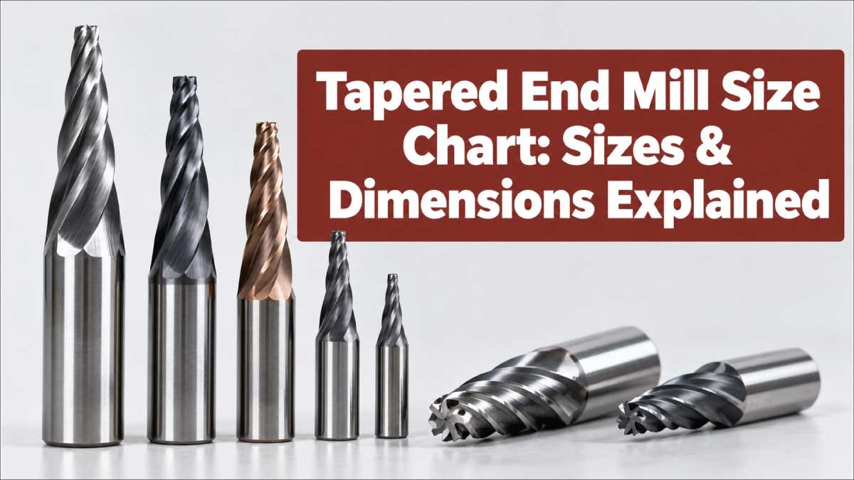
Choosing the right tapered end mill requires more than selecting a cutter diameter. The taper angle, cutting diameter, shank diameter, flute length, overall length, number of flutes, and cutting depth all affect how the tool performs.
A tapered end mill gradually changes diameter along the cutting portion, allowing it to machine angled walls, cavities, molds, dies, and other features where a straight end mill may not provide the desired geometry. However, there is no single universal tapered end mill size standard covering every manufacturer and application.
This tapered end mill size chart explains the dimensions you are most likely to encounter, how taper affects the cutter profile, how to measure a tapered end mill, and how to choose the appropriate tool for CNC machining.
What Is a Tapered End Mill?
A tapered end mill is a rotary cutting tool whose cutting diameter changes progressively along its length. Instead of having parallel sides like a conventional straight end mill, the cutting portion is formed at a specified taper.
The taper may extend over the complete cutting length or over a particular portion of the tool. Depending on the design, the cutter may become narrower toward the tip or wider toward the shank.
Tapered end mills are commonly used for machining:
- Mold and die cavities
- Sloped walls
- Drafted surfaces
- Deep pockets
- Complex 3D contours
- Recesses and cavities
- Hardened or difficult-to-machine components
- Fine finishing operations
The taper provides additional clearance and can improve tool access in deep or angled features.
Tapered vs. Straight End Mills
A straight end mill maintains approximately the same cutting diameter along its cutting section. A tapered end mill does not.
| Feature | Straight End Mill | Tapered End Mill |
|---|---|---|
| Side profile | Parallel | Angled |
| Cutting diameter | Generally constant | Changes along taper |
| Typical use | Slots, pockets, profiles | Angled walls, cavities, 3D features |
| Side-wall geometry | Vertical | Tapered |
| Deep-cavity access | Application dependent | Often advantageous |
| Tool selection | Diameter-focused | Diameter and taper-focused |
The important point is that tapered end mill dimensions must be considered together. A cutter with the correct tip diameter but the wrong taper angle may produce an incorrect feature.
Tapered End Mill Size Chart
There is no universal size chart that applies to every tapered end mill because manufacturers offer different cutter geometries, taper angles, shank standards, flute lengths, coatings, and metric or inch sizes.
The following chart is therefore a nominal size-selection guide, not a manufacturer-specific dimensional standard. It shows common cutter diameter classes that may be encountered when selecting tapered tooling.
| Nominal Cutting Diameter | Approx. Inch Equivalent | Common Machining Role | Typical Consideration |
|---|---|---|---|
| 2 mm | 0.079 in | Fine features | Low radial engagement |
| 3 mm | 0.118 in | Small cavities | Requires careful setup |
| 4 mm | 0.157 in | Small profiles | Useful for detailed work |
| 5 mm | 0.197 in | General small features | Balance of access and rigidity |
| 6 mm | 0.236 in | General machining | Common small-tool class |
| 8 mm | 0.315 in | Pockets and contours | Greater rigidity than smaller tools |
| 10 mm | 0.394 in | General profiling | Suitable where access permits |
| 12 mm | 0.472 in | Larger cavities | Higher material-removal potential |
| 16 mm | 0.630 in | Heavy profiling | Requires sufficient machine capacity |
| 20 mm | 0.787 in | Large features | More suitable for larger workpieces |
These diameters describe the nominal cutting size, not the complete physical dimensions of a specific tool.
Always verify the manufacturer’s drawing before ordering when a particular taper, shank, flute length, or overall length is required.
Key Tapered End Mill Dimensions
Understanding the terminology used on tool drawings makes it much easier to compare cutters.
Cutting Diameter
The cutting diameter is the diameter across the cutting portion at a specified location.
With a tapered cutter, this measurement cannot always be represented by one diameter for the entire cutting length. A drawing may specify a diameter at the small end, large end, or another reference point.
For example, a tool might have a smaller tip diameter and a larger diameter toward the shank. The difference between these diameters determines how quickly the tool expands.
Taper Angle
The taper angle describes how much the cutter’s side moves away from its centerline.
It is one of the most important dimensions when machining an angled wall because the cutter’s taper needs to correspond with the intended geometry.
A small change in taper angle can create a noticeable difference over a deep cavity.
Shank Diameter
The shank is the portion held by the tool holder, collet, or chuck.
Common shank sizes vary according to tooling systems and manufacturers. Metric tools may use dimensions such as 6 mm, 8 mm, 10 mm, 12 mm, or larger, while inch tooling can use fractional or decimal shank sizes.
The shank must match the holding system correctly.
Flute Length
Flute length is the portion of the cutter containing the cutting edges.
A longer flute allows greater cutting depth, but excessive tool length can reduce rigidity and increase the potential for vibration.
For this reason, the longest possible tool is not automatically the best choice.
Overall Length
Overall length measures the complete tool from the cutting tip to the end of the shank.
It affects tool reach and clearance inside the machine, but it should not be confused with usable cutting length.
Number of Flutes
Tapered end mills may be produced with different flute counts.
The appropriate number depends on material, cutting conditions, chip evacuation requirements, and the manufacturer’s recommended application.
More flutes can provide additional cutting edges, while fewer flutes can offer more space for chip evacuation.
Taper Angle and Diameter Relationship
The geometry of a tapered cutter can be understood by looking at how its diameter changes over a given length.
For a symmetrical taper, the diameter difference between two points is related to the taper angle and the axial distance between those points.
A simplified geometric relationship can be expressed as:
D₂ − D₁ = 2L × tan(θ)
Where:
- D₁ = diameter at the first measurement point
- D₂ = diameter at the second measurement point
- L = axial distance between the points
- θ = half-angle of the taper
This relationship is useful for understanding taper geometry, but actual tooling may use manufacturer-specific definitions for taper angle, included angle, or taper specification.
Included Angle vs. Half-Angle
One common source of confusion is whether a catalog gives the included taper angle or the angle relative to the centerline.
For example, an included angle describes the full angle between opposite tapered sides, whereas a half-angle describes one side relative to the tool axis.
Always check how the manufacturer defines the angle before comparing two tools.
Common Tapered End Mill Types
Tapered end mills are available in several configurations. The best choice depends on the workpiece geometry and machining operation.
Tapered Ball Nose End Mill
A tapered ball nose end mill combines a tapered side profile with a rounded cutting end.
It is particularly useful for:
- 3D contouring
- Mold cavities
- Sculpted surfaces
- Die machining
- Finishing complex profiles
The rounded tip allows the cutter to follow curved surfaces while the tapered body provides additional rigidity and access.
Tapered Flat End Mill
A tapered flat end mill has a flat cutting end rather than a spherical nose.
It can be useful when machining:
- Flat-bottom pockets
- Drafted walls
- Angled cavities
- Roughing operations
- Features requiring a defined flat cutting area
The flat end geometry can make it more suitable than a ball nose cutter when a flat floor is required.
Tapered Carbide End Mill
Carbide tapered end mills are widely used for CNC machining because carbide can provide high hardness and wear resistance when used under appropriate cutting conditions.
They are available in different geometries and coatings for different materials.
Tapered High-Speed Steel End Mill
High-speed steel tooling can provide useful toughness and is available in tapered configurations.
Its suitability depends on the material, machine, cutting speed, tool geometry, and required productivity.
How to Measure a Tapered End Mill
Accurate measurement is important when identifying an existing cutter or replacing a damaged tool.
Step 1: Measure the Shank
Use a suitable precision measuring instrument to determine the shank diameter.
Take the measurement on a clean, undamaged section of the shank rather than on the cutting edges.
Record the value in either millimeters or inches.
Step 2: Measure the Cutting Diameters
Because the cutter is tapered, measure the diameter at clearly defined points.
For example:
- Diameter near the tip
- Diameter near the larger end of the taper
- Diameter at a specified axial distance
Record both the diameter and the location where it was measured.
Step 3: Measure the Taper Length
Measure the axial distance over which the taper occurs.
Do not automatically use the entire flute length because some cutters have a tapered region that does not correspond exactly to the full cutting length.
Step 4: Determine the Taper
If the end diameters and taper length are known, the taper geometry can be calculated.
However, identification should ideally be compared with the manufacturer’s dimensional drawing because cutter geometry can include radii, reliefs, edge preparations, and other features.
Step 5: Record Overall Length and Flute Length
Measure the complete tool length and the usable flute length separately.
This prevents confusion when comparing replacement tools.
Also Read:
How to Choose the Correct Tapered End Mill Size
Selecting a tapered cutter starts with the geometry of the feature you need to machine.
Match the Taper to the Part
The taper angle should correspond to the required wall geometry when the cutter is intended to directly produce that angle.
If the part requires a particular draft angle, verify the relationship between the cutter’s taper and the finished surface.
Choose the Smallest Practical Tip Diameter
A smaller tip can reach narrow areas and detailed features, but smaller tools generally have less cross-sectional strength.
Do not choose an extremely small diameter simply because it provides better access.
Consider:
- Required feature size
- Material hardness
- Cutting depth
- Machine rigidity
- Tool stick-out
- Feed and speed capability
Use the Shortest Practical Tool
Tool overhang has a major effect on rigidity.
When two tools can reach the same feature, the shorter setup is generally easier to control.
A long-reach tapered end mill may be necessary for deep cavities, but unnecessary extension should be avoided.
Check the Shank and Holder
The shank must be compatible with the collet, chuck, hydraulic holder, shrink-fit holder, or other tooling system being used.
The tool should be held securely without relying on an incompatible diameter or improvised setup.
Also Read:
Tapered End Mill Size Selection by Application
Different machining tasks place different demands on the cutter.
| Application | Preferred Geometry | Important Dimension | Main Selection Concern |
|---|---|---|---|
| Deep cavity | Tapered ball nose or suitable tapered profile | Reach and taper | Clearance |
| 3D contouring | Tapered ball nose | Tip diameter | Surface detail |
| Angled wall | Tapered flat or suitable profile | Taper angle | Wall geometry |
| Fine detail | Small tapered cutter | Tip diameter | Tool strength |
| Rough cavity work | Robust tapered cutter | Diameter and flute length | Rigidity |
| Finishing | Fine ball nose or tapered profile | Tip radius | Surface quality |
| Mold machining | Tapered ball nose | Taper and tip size | Geometry accuracy |
The tool’s coating, substrate, helix, flute count, and edge preparation should also be considered according to the material being machined.
Metric and Inch Tapered End Mill Sizes
Tapered end mills are manufactured in both metric and inch-based dimensions.
Metric tools are commonly identified by dimensions in millimeters, while inch tools may use decimal or fractional measurements.
| Metric Size | Approximate Inch Value | Measurement System |
|---|---|---|
| 3 mm | 0.118 in | Metric |
| 4 mm | 0.157 in | Metric |
| 6 mm | 0.236 in | Metric |
| 8 mm | 0.315 in | Metric |
| 10 mm | 0.394 in | Metric |
| 12 mm | 0.472 in | Metric |
| 16 mm | 0.630 in | Metric |
| 20 mm | 0.787 in | Metric |
The inch values shown are mathematical conversions, not necessarily standard inch tool sizes.
A metric-to-inch conversion should therefore not be treated as proof that an equivalent cutter is commercially available.
Also Read:
Tapered End Mill Materials and Coatings
Tool material affects durability, cutting performance, and suitability for different workpieces.
Carbide
Solid carbide is common for precision CNC cutting tools.
Its hardness and stiffness make it suitable for many demanding machining applications when the cutter and cutting parameters are properly matched to the material.
High-Speed Steel
High-speed steel provides a different balance of toughness, hardness, and cost.
It can be appropriate for certain machining environments, particularly where the operating conditions favor its characteristics.
Coatings
Tapered end mills may use coatings designed to improve wear resistance, reduce friction, or improve performance in particular materials.
Coating selection should be based on the workpiece and cutting application rather than assuming one coating is universally superior.
Common Tapered End Mill Problems
Incorrect dimensions are not the only reason a tapered cutter may produce poor results.
Incorrect Taper Angle
A cutter with the wrong taper can create a wall angle that does not match the intended part geometry.
This is particularly important in mold and die work.
Excessive Tool Stick-Out
A long extension increases the leverage acting on the cutter and can contribute to vibration, deflection, and poor surface finish.
Use only the necessary reach.
Wrong Tip Diameter
A cutter may physically fit into a cavity but still be too large for the required detail.
Always compare the cutter’s tip diameter with the smallest feature radius or width.
Insufficient Clearance
The cutter body and holder must have enough clearance from surrounding walls.
A tapered tool can improve access, but it does not eliminate the need to check the complete toolpath and holder geometry.
Incorrect Cutting Parameters
Even a correctly sized cutter can perform poorly when spindle speed, feed rate, depth of cut, radial engagement, or coolant strategy is inappropriate.
Use cutting data appropriate for the specific tool, workpiece, machine, and setup.
Tapered End Mill vs. Ball Nose End Mill
These tools can overlap in applications, but their geometries are different.
A tapered ball nose end mill has both a tapered body and a rounded cutting tip. A conventional ball nose cutter may have a constant-diameter body with a spherical end.
Tapered ball nose tools are especially useful when deep 3D surfaces require both reach and rigidity.
The choice depends on the geometry rather than simply the desired surface finish.
Tips for Buying a Tapered End Mill
Before purchasing a cutter, check the complete dimensional specification rather than relying only on the advertised diameter.
Look for:
Tip or cutting diameter
Large-end cutting diameter
Taper angle
Shank diameter
Flute length
Overall length
Flute count
Tool material
Coating
Helix geometry
End geometry
Recommended workpiece materials
Manufacturer cutting data
If the tool will be used to produce a precision taper, the taper specification is especially important.
Two cutters with the same nominal tip diameter can behave very differently if their taper angles or cutting lengths differ.
Frequently Asked Questions
What is the most important tapered end mill dimension?
There is no single dimension that is always most important. The tip diameter, taper angle, flute length, shank diameter, and overall reach all affect tool selection.
For an angled wall, taper angle may be critical. For a narrow cavity, tip diameter may matter more.
Are tapered end mill sizes standardized?
Not as one universal dimensional system. Manufacturers offer different combinations of diameters, taper angles, shank sizes, lengths, flute counts, and cutting geometries.
Always use the manufacturer’s drawing when an exact tool dimension is required.
What is a tapered ball nose end mill used for?
It is commonly used for 3D contouring, mold and die machining, deep cavities, sculpted surfaces, and complex finishing operations.
Its tapered body can provide useful clearance and rigidity while the rounded tip follows curved surfaces.
How do I measure a tapered end mill?
Measure the shank diameter, cutting diameter at defined locations, taper length, overall length, and flute length.
Because the cutter diameter changes along the taper, always record where each diameter was measured.
Is a larger tapered end mill better?
Not necessarily. A larger cutter may provide greater rigidity and material removal capability, but it may not fit into small features or tight cavities.
Choose the largest practical cutter that satisfies the geometry and machining requirements.
Can a tapered end mill machine straight walls?
It can physically remove material from a wall, but its tapered geometry naturally produces an angled profile when the side of the cutter forms the finished surface.
If a precise vertical wall is required, a suitable straight-sided tool may be more appropriate.
What determines tapered end mill flute length?
Flute length is selected according to the required cutting depth and tool geometry. A longer flute provides greater cutting reach, but excessive length can reduce rigidity.
The objective is to use sufficient flute length without unnecessary tool extension.
Key Takeaways
A tapered end mill is defined by more than its nominal diameter. Its taper angle, diameter progression, shank size, flute length, overall length, tip geometry, and flute configuration all contribute to how it performs.
When using a tapered end mill size chart, remember that the listed diameter is only one part of the tool specification. Manufacturer drawings should be used whenever an exact taper, length, or dimensional fit is required.
For reliable tool selection:
- Match the taper angle to the required geometry.
- Select a practical tip diameter for the smallest feature.
- Use adequate but not excessive flute length.
- Keep tool stick-out as short as practical.
- Confirm shank and holder compatibility.
- Consider the workpiece material and tool substrate.
- Follow application-specific cutting data.
- Verify exact dimensions against the manufacturer’s specification.
The right tapered end mill balances access, rigidity, geometry, cutting performance, and dimensional requirements rather than simply choosing the smallest or largest available cutter.
Conclusion
A tapered end mill size chart is useful for comparing cutter diameters and understanding the dimensional options available, but exact tool selection requires more than diameter alone. Taper angle, tip size, flute length, shank diameter, overall length, and end geometry should all be considered together.
For precision CNC machining, identify the required part geometry first, then choose a cutter that provides the necessary reach and taper while maintaining adequate rigidity. When exact dimensions matter, always confirm the complete tool drawing and specifications before machining.

Engineer Hassan is a Mechanical Engineer with 16+ years of hands-on experience in mechanical hardware, fasteners, and workshop tools. He focuses on size selection, thread identification, and measurement, helping users choose the correct components with accuracy and safety.