Gears are one of the most important mechanical components used in machines, vehicles, industrial equipment, and power transmission systems. They transfer motion and torque between rotating shafts while controlling speed and direction. Choosing the correct gear size is essential because improper sizing can reduce efficiency, increase wear, and cause mechanical failure.
This complete guide explains gear dimensions, gear ratios, pitch diameter, module size, tooth count, and common gear types. You will also find detailed gear size charts and practical tips for selecting the right gear for your application.
What Is a Gear?
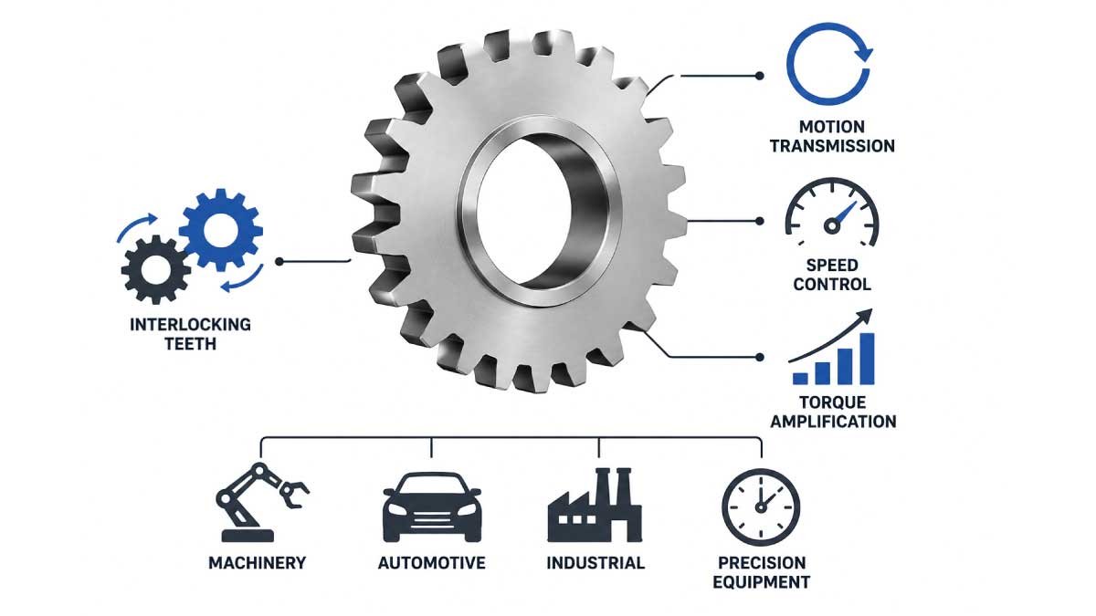
A gear is a circular mechanical component designed with evenly spaced teeth that interlock with another gear to transmit motion and force. Gears are essential in mechanical systems because they control speed, direction, and torque efficiently. They are widely used in machines to improve performance, reduce effort, and ensure smooth power transfer between connected parts.
A gear is a rotating mechanical component with teeth that mesh with another gear to transmit power. Gears help machines:
- Increase or decrease speed
- Change rotational direction
- Transfer torque
- Improve mechanical efficiency
Gears are used in:
- Automobiles
- Industrial machinery
- Clocks
- Robotics
- Power tools
- Bicycles
- Aerospace systems
Understand The Gear Measurements
Understanding gear measurements is essential before using a gear size chart because each dimension directly affects performance and compatibility. These measurements define how gears interact, their strength, and speed control in mechanical systems. Knowing these basics helps engineers and technicians select the right gear for efficient power transmission and smooth machine operation.
1. Number of Teeth
The number of teeth is one of the most important gear characteristics because it determines the gear ratio and overall speed output. It also affects torque and rotational balance. A higher or lower tooth count changes how fast or slow connected gears rotate and how power is distributed between them.
Example:
A gear with 40 teeth rotating another gear with 20 teeth creates a 2:1 ratio.
More teeth usually mean larger gear diameter.
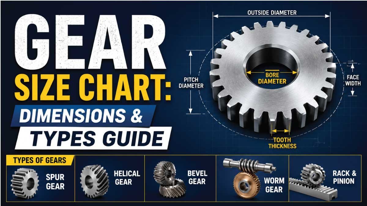
2. Pitch Diameter
Pitch diameter is an imaginary circular line where two gears effectively mesh and transfer motion. It is a key reference point for gear design and calculations. This measurement helps determine gear ratios and ensures proper alignment between meshing gears for smooth and efficient power transmission.
3. Outside Diameter
Outside diameter refers to the full diameter of a gear measured from the tip of one tooth to the opposite outer edge. It represents the maximum size of the gear and is important for fitting it into assemblies where space limitations must be considered.
4. Bore Size
The bore size is the central hole of the gear that fits onto a shaft. It ensures the gear is securely mounted and rotates properly with the shaft. Bore size must match the shaft diameter precisely to avoid slipping, vibration, or mechanical failure during operation.
5. Module
Module is a standard metric measurement used to define the size of gear teeth. It indicates how large or small each tooth is and helps maintain consistency in gear design. Larger module values mean bigger, stronger teeth, which are suitable for heavy-load applications.
Formula:
Module = Pitch Diameter ÷ Number of Teeth
Larger module values indicate larger teeth.
6. Diametral Pitch (DP)
Diametral pitch is commonly used in imperial gear systems.
Formula:
DP = Number of Teeth ÷ Pitch Diameter
Higher DP means smaller teeth.
Standard Spur Gear Size Chart
Spur gears are the most widely used type of gear because they are simple, efficient, and cost-effective. They transmit power between parallel shafts with minimal loss. This chart helps identify standard sizes based on number of teeth, module, pitch diameter, and outside diameter for accurate selection in mechanical applications.
| Number of Teeth | Module | Pitch Diameter | Outside Diameter |
|---|---|---|---|
| 12 | 1 | 12 mm | 14 mm |
| 16 | 1 | 16 mm | 18 mm |
| 20 | 1 | 20 mm | 22 mm |
| 24 | 1.5 | 36 mm | 39 mm |
| 30 | 1.5 | 45 mm | 48 mm |
| 40 | 2 | 80 mm | 84 mm |
| 50 | 2 | 100 mm | 104 mm |
| 60 | 2.5 | 150 mm | 155 mm |
| 80 | 3 | 240 mm | 246 mm |
Metric Gear Size Chart
Metric gears are widely used across global industries because they follow standardized SI measurements. They ensure compatibility, precision, and easy replacement in mechanical systems. This chart shows common module sizes, typical tooth ranges, and where each type is generally used in engineering and industrial applications.
Metric gears are commonly used worldwide.
| Module | Common Tooth Counts | Typical Applications |
|---|---|---|
| 0.5 | 10–60 | Small instruments |
| 1 | 12–80 | Robotics and automation |
| 1.5 | 15–100 | Industrial drives |
| 2 | 20–120 | Machinery |
| 3 | 20–150 | Heavy-duty systems |
| 4 | 30–200 | Large industrial equipment |
Gear Ratio Chart
Gear ratio defines the relationship between the driving gear and the driven gear. It directly affects speed and torque output in mechanical systems. A higher gear ratio increases torque while reducing speed, while a lower ratio increases speed but reduces torque, depending on application needs.
| Driving Gear | Driven Gear | Gear Ratio |
|---|---|---|
| 20 Teeth | 40 Teeth | 1:2 |
| 30 Teeth | 60 Teeth | 1:2 |
| 15 Teeth | 45 Teeth | 1:3 |
| 40 Teeth | 20 Teeth | 2:1 |
| 50 Teeth | 25 Teeth | 2:1 |
Higher ratios increase torque but reduce speed.
Standard Spur Gear Size Chart pdf
A standard spur gear size chart PDF helps engineers, machinists, and students quickly find common gear dimensions, including teeth count, module, pitch diameter, and outside diameter. These charts are useful for gear selection, mechanical design, manufacturing, and maintenance work. A printable PDF format makes it easy to use in workshops, factories, and technical projects.
Gear_Size_Charts PDF
You May Also Like This:
Types of Gears
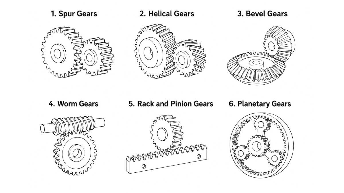
Different gear types are designed for different applications depending on speed, torque, direction, and space requirements. Each gear type has a unique structure and working principle that makes it suitable for specific mechanical systems. Understanding these types helps in selecting the right gear for efficiency, durability, and performance in machines.
1. Spur Gears
Spur gears are the simplest and most commonly used gear type. They have straight teeth and work on parallel shafts. Their design allows efficient power transmission with minimal energy loss, making them ideal for basic mechanical systems where noise and high-speed limitations are not major concerns.
Advantages:
- Simple design
- Easy manufacturing
- High efficiency
Applications:
- Industrial machines
- Conveyors
- Gearboxes
2. Helical Gears
Helical gears have angled teeth, which allow smoother and quieter operation compared to spur gears. The angled design increases contact between teeth, improving load distribution and making them suitable for high-speed and heavy-load applications where reduced vibration is important.
Benefits:
- Quiet performance
- Higher load capacity
- Reduced vibration
Used in:
- Automotive transmissions
- Heavy machinery
3. Bevel Gears
Bevel gears are designed to transfer power between intersecting shafts, usually at a 90-degree angle. Their conical shape allows efficient directional change in motion, making them essential in systems where power needs to be redirected between different axes.
Applications:
- Differential systems
- Power tools
- Industrial drives
4. Worm Gears
Worm gears consist of a screw-like shaft that drives a gear wheel. This setup provides very high reduction ratios and compact design. They are often used when speed reduction and torque multiplication are required in a small space, along with self-locking capability for safety.
Advantages:
- High reduction ratios
- Compact design
- Self-locking capability
Applications:
- Elevators
- Conveyor systems
- Steering systems
5. Rack and Pinion Gears
Rack and pinion systems convert rotational motion into linear motion. The circular pinion gear engages with a straight rack to create precise movement, making it highly useful in steering and positioning systems where accuracy is important.
Common uses:
- Steering systems
- CNC machines
- Sliding gates
6. Planetary Gears
Planetary gear systems consist of multiple gears rotating around a central sun gear. This compact and efficient design allows high torque transmission while maintaining stability. They are widely used in advanced mechanical and aerospace applications due to their strength and versatility.
Benefits:
- Compact design
- High torque capacity
- Excellent efficiency
Used in:
- Automatic transmissions
- Robotics
- Aerospace systems
Gear Materials
Material selection plays a major role in determining gear durability, strength, and overall performance. Different materials are chosen based on load requirements, operating environment, noise level, and cost. A suitable material ensures longer life, smoother operation, and better efficiency in mechanical systems.
1. Steel Gears
Steel is the most widely used material for gears because of its excellent strength and durability. It can handle heavy loads and high stress without deforming easily, making it ideal for demanding mechanical applications where reliability and long service life are essential.
Advantages:
- High strength
- Wear resistance
- Long lifespan
Applications:
- Industrial equipment
- Automotive systems
2. Stainless Steel Gears
Stainless steel gears are specially designed to resist rust and corrosion, making them suitable for environments where moisture, chemicals, or hygiene are important factors. They offer both durability and cleanliness, ensuring reliable performance in sensitive applications.
Used in:
- Food processing
- Marine equipment
- Medical devices
3. Brass Gears
Brass gears are known for their smooth and quiet operation. They also provide good corrosion resistance and are often used in precision instruments where low noise and smooth movement are more important than heavy load capacity.
Applications:
- Clocks
- Instruments
- Decorative mechanisms
4. Plastic Gears
Plastic gears are lightweight, cost-effective, and operate quietly compared to metal gears. They are ideal for low-load applications and environments where noise reduction and corrosion resistance are important factors.
Benefits:
- Quiet operation
- Corrosion resistance
- Low manufacturing cost
Common uses:
- Printers
- Toys
- Household appliances
You May Also Like This:
Gear Tooth Profiles
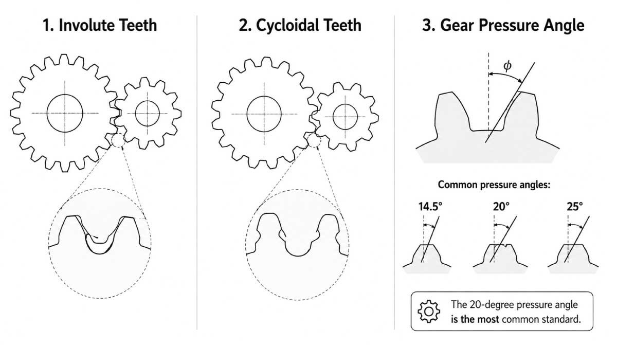
Gear tooth profiles define the shape of the teeth, which directly affects how smoothly gears mesh, transmit power, and reduce wear. A well-designed tooth profile improves efficiency, reduces noise, and ensures consistent motion in mechanical systems. Different profiles are used depending on precision, speed, and application requirements.
1. Involute Teeth
Involute tooth profiles are the most widely used in modern gears because they provide smooth and reliable power transmission. Their shape ensures consistent contact between teeth even if slight misalignment occurs, making them ideal for high-performance mechanical systems.
Advantages:
- Smooth meshing
- Consistent motion
- Easier manufacturing
2. Cycloidal Teeth
Cycloidal gears use a more complex tooth shape and are mainly found in precision instruments. They are less common in heavy machinery but are valued for their accuracy and smooth operation in low-load, high-precision applications such as timekeeping devices.
3. Gear Pressure Angle
The pressure angle is the angle at which gear teeth engage during contact. It plays a key role in determining gear strength, load distribution, and smoothness of operation. A higher or lower pressure angle can significantly affect performance and durability.
Common pressure angles:
- 14.5°
- 20°
- 25°
The 20-degree pressure angle is the most common standard.
Gear Backlash Explained
Backlash is the small intentional gap between meshing gear teeth. It is necessary for proper gear operation because it allows space for lubrication and thermal expansion. However, it must be carefully controlled to maintain accuracy and smooth motion.
Proper backlash prevents:
- Binding
- Excessive wear
- Heat buildup
Too much backlash may cause vibration and noise.
Gear Efficiency
Gear efficiency refers to how effectively mechanical power is transferred from one gear to another with minimal loss. High efficiency means less energy waste and smoother operation, which is essential in performance-driven mechanical systems.
Factors affecting efficiency:
- Lubrication
- Alignment
- Tooth design
- Material quality
Spur and helical gears often achieve efficiencies above 95%.
Gear Load Capacity
Gear load capacity determines how much force a gear can handle without failing or deforming. It depends on design, material strength, and size. Proper selection ensures safe and long-lasting performance under working conditions.
Factors affecting load capacity:
- Tooth size
- Material
- Heat treatment
- Gear width
Larger gears with wider teeth typically handle heavier loads.
You May Also Like This:
Gear Lubrication
Lubrication is essential for reducing friction, heat, and wear between gear teeth. It improves efficiency, extends gear life, and ensures smooth operation under different working conditions. The choice of lubricant depends on speed, load, and environmental factors.
1. Grease Lubrication
Grease lubrication is commonly used in low-speed and enclosed gear systems. It stays in place for longer periods, reducing the need for frequent maintenance while providing adequate protection against wear.
Advantages:
- Simple maintenance
- Good sealing properties
2. Oil Lubrication
Oil lubrication is preferred for high-speed and high-load gear systems. It provides better cooling and reduces friction more effectively, making it suitable for industrial and automotive applications where performance and heat control are critical.
Benefits:
- Better cooling
- Reduced friction
- Longer gear life
How to Measure Gear Size
Measuring gear size correctly is important to ensure proper fit, smooth operation, and compatibility with other mechanical parts. Accurate measurements help in selecting the right replacement gear and avoiding performance issues in machines, vehicles, and industrial equipment.
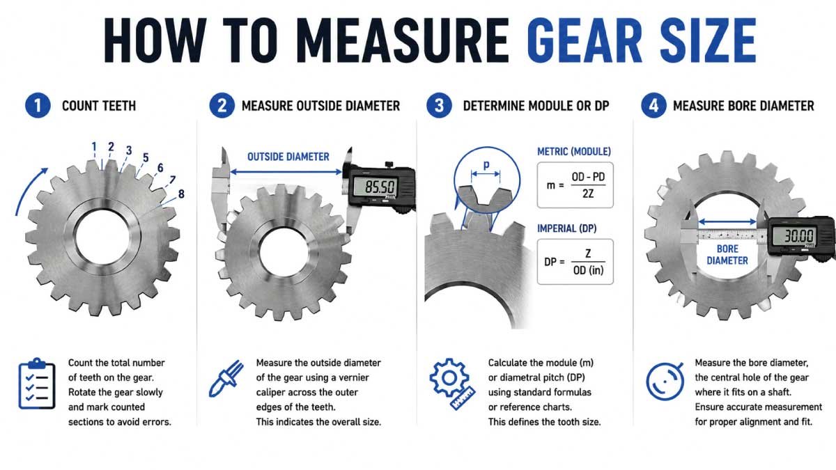
Step 1: Count Teeth
The first and most basic step in measuring gear size is counting the total number of teeth on the gear. Each tooth plays a role in motion transfer, so accuracy is important. Rotate the gear slowly and mark counted sections to avoid errors during measurement.
Step 2: Measure Outside Diameter
Next, measure the outside diameter of the gear using a vernier caliper for better accuracy. Place the caliper across the outer edges of the teeth. This measurement helps identify the gear’s overall size and is often used along with tooth count for proper specification matching.
Step 3: Determine Module or DP
The module (metric system) or diametral pitch (imperial system) defines the tooth size of the gear. You can calculate it using standard formulas or reference charts. Matching this value ensures that gears mesh correctly without slipping, excessive wear, or noise during operation.
Step 4: Measure Bore Diameter
Finally, measure the bore diameter, which is the central hole where the gear fits onto a shaft. Use precise measuring tools to ensure accuracy. This step is essential for proper alignment and secure fitting, preventing loosening or mechanical failure during operation.
Common Gear Applications
Gears are used in almost every mechanical industry because they efficiently transfer power, control speed, and adjust torque. Their versatility makes them essential in both simple machines and advanced engineering systems. From vehicles to robotics, gears ensure smooth and controlled mechanical motion in a wide range of applications.
1. Automotive Industry
The automotive industry relies heavily on gears for efficient vehicle performance. Gears help control speed, torque, and direction, allowing smooth driving and safe handling. Without gears, vehicles would not be able to adapt power effectively from the engine to the wheels.
Automobiles use gears in:
- Transmissions
- Differentials
- Steering systems
2. Industrial Machinery
Industrial systems use gears to handle heavy loads and continuous operation. They are essential in machines that require precise power transmission and durability under demanding conditions. Gears ensure smooth operation of equipment used in production, processing, and material handling.
Industrial systems use gears for:
- Conveyors
- Pumps
- Compressors
- Manufacturing equipment
3. Robotics
Robotics systems depend on precision gears for accurate and controlled movement. Gears help robots perform complex tasks with high repeatability and stability. Compact and efficient gear systems like planetary gears are widely used in robotic joints and actuators.
Planetary gears are especially popular.
4. Aerospace Industry
In aerospace applications, gears must be lightweight, strong, and highly precise. They are used in systems where reliability is critical, such as flight control and engine mechanisms. These gears are designed to perform under extreme conditions with maximum efficiency.
Applications include:
- Actuators
- Landing gear systems
- Engines
5. Bicycle Systems
Bicycle gears allow riders to adjust speed and pedaling effort depending on terrain and riding conditions. They make cycling more efficient by balancing force and speed, especially during uphill climbs or fast riding on flat surfaces.
Common Gear Problems
Improper gear sizing, poor maintenance, or incorrect installation can lead to several mechanical issues. These problems reduce efficiency, increase wear, and may eventually cause system failure if not addressed properly.
1. Gear Wear
Gear wear occurs when tooth surfaces gradually degrade due to friction and load. It is usually caused by insufficient lubrication, misalignment, or excessive mechanical stress over time.
Caused by:
- Poor lubrication
- Misalignment
- Excessive loads
2. Tooth Breakage
Tooth breakage happens when gears are exposed to sudden or heavy impact loads beyond their capacity. This type of failure can stop machine operation completely and may damage surrounding components.
3. Overheating
Overheating occurs when there is excessive friction between gear teeth, often due to poor lubrication or overload conditions. High temperatures can reduce gear life and weaken material strength.
4. Excessive Noise
Unusual gear noise is often a sign of mechanical issues that need immediate attention. It usually indicates improper alignment, damaged teeth, or incorrect backlash settings.
Noise often indicates:
- Improper alignment
- Damaged teeth
- Incorrect backlash
Gear Heat Treatment
Heat treatment is a process used to improve gear strength, hardness, and resistance to wear. It enhances the mechanical properties of gears, allowing them to perform better under heavy loads and harsh working conditions.
Common methods include:
- Carburizing
- Induction hardening
- Nitriding
Heat-treated gears last longer under heavy loads.
Advantages of Proper Gear Sizing
Proper gear sizing is essential for achieving smooth, efficient, and reliable mechanical performance. When gears are correctly matched in size and specification, they operate with less stress and improved accuracy. This not only enhances machine efficiency but also reduces maintenance needs and prevents early failures in mechanical systems.
1. Better Efficiency
Proper gear sizing ensures accurate meshing between teeth, which minimizes energy loss during power transmission. When gears are correctly selected, they transfer motion more effectively, reducing friction and improving overall system performance in both light and heavy-duty applications.
2. Longer Service Life
Correctly sized gears experience less wear and mechanical stress during operation. This reduces surface damage and extends the lifespan of both gears and connected components, resulting in lower replacement costs and improved machine reliability over time.
3. Reduced Noise
Well-matched gears operate more smoothly and produce less vibration. Proper sizing ensures stable contact between teeth, which significantly reduces operational noise and creates quieter performance, especially in precision equipment and industrial machinery.
4. Improved Torque Transfer
Correct gear ratios allow efficient transfer of torque based on application requirements. Proper sizing ensures that mechanical power is distributed effectively, helping machines perform optimally under different load conditions without unnecessary strain.
You May Also Like This:
Gear Maintenance Tips
Regular maintenance is essential to keep gears functioning efficiently and to prevent premature failure. Proper inspection, lubrication, and alignment help maintain performance, reduce wear, and ensure long-term reliability in mechanical systems.
1. Inspect Gear Teeth
Regular inspection helps identify early signs of damage before serious failure occurs. Checking gear teeth ensures that problems are detected early and corrected in time to avoid costly repairs or breakdowns.
Check for:
- Cracks
- Wear
- Chips
- Pitting
2. Maintain Lubrication
Proper lubrication reduces friction between gear teeth and prevents overheating. It is important to replace old or contaminated lubricants regularly to maintain smooth operation and reduce wear on gear surfaces.
3. Monitor Alignment
Misaligned gears create uneven contact between teeth, leading to faster wear and reduced efficiency. Regular alignment checks ensure smooth operation and prevent unnecessary mechanical stress on the system.
4. Prevent Contamination
Dust, dirt, and debris can severely damage gear teeth and reduce performance. Keeping gear systems clean and protected from contamination helps maintain efficiency and extends service life.
Gear Standards
Gear standards define the specifications, dimensions, and quality requirements for gear manufacturing. These standards ensure compatibility between different systems and maintain consistency in performance, safety, and reliability across industries worldwide.
| Standard | Description |
|---|---|
| AGMA | American Gear Manufacturers Association |
| ISO Standards | International gear standards |
| DIN Standards | German industrial standards |
These standards ensure compatibility and quality.
Conclusion
Gears are essential components in automotive systems, industrial machinery, robotics, and countless mechanical devices. Understanding gear sizes, tooth counts, modules, pitch diameters, and gear ratios helps ensure efficient and reliable performance.
Using a proper gear size chart makes it easier to select compatible gears for your application. Correct gear sizing improves torque transfer, reduces wear, minimizes noise, and extends equipment lifespan. Whether you are working with spur gears, helical gears, bevel gears, or planetary systems, choosing the right gear dimensions is critical for long-term mechanical success.
FAQs:
What is the standard gear size?
Standard gear size is not fixed because it depends on design requirements, tooth count, module, diametral pitch, and application type. Different industries use different standards for machinery, automotive, and industrial systems. Engineers select gear size based on torque, speed, and load conditions to ensure smooth and efficient mechanical power transmission.
How do I calculate gear ratio?
Gear ratio is calculated by dividing the number of teeth on the driven gear by the number of teeth on the driving gear. This ratio shows how speed and torque are transferred between gears. A higher ratio increases torque but reduces speed, while a lower ratio increases speed but reduces torque output.
What is module in gears?
Module is a metric unit used to define gear tooth size. It is calculated by dividing the pitch diameter by the number of teeth. A larger module means bigger and stronger teeth, suitable for heavy loads. It helps ensure proper meshing between gears and is widely used in metric gear design systems.
Which gear type is strongest?
Helical and planetary gears are generally considered the strongest because they distribute load more evenly across multiple teeth. Helical gears provide smoother engagement, while planetary systems handle high torque in compact spaces. Spur gears are simpler but less strong under heavy loads compared to these advanced gear types in industrial applications.
Why are gears lubricated?
Gears are lubricated to reduce friction between moving teeth, which helps minimize wear and heat generation. Proper lubrication improves efficiency, reduces noise, and extends gear life. It also protects against rust and surface damage, ensuring smooth operation under high-speed and high-load conditions in mechanical and industrial systems.

Engineer Hassan is a Mechanical Engineer with 16+ years of hands-on experience in mechanical hardware, fasteners, and workshop tools. He focuses on size selection, thread identification, and measurement, helping users choose the correct components with accuracy and safety.