
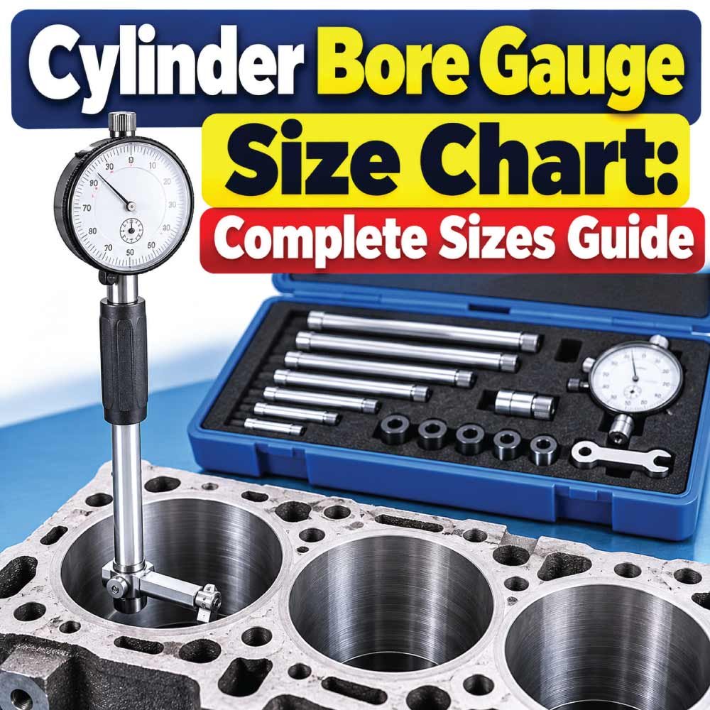
A cylinder bore gauge is a precision measuring tool used to determine the inside diameter, taper, and out-of-round condition of a cylinder or bore. Choosing the correct gauge size matters because a gauge must physically reach the required bore range while providing enough resolution for the inspection task.
This cylinder bore gauge size chart explains common measuring ranges, gauge dimensions, types, setup methods, reading techniques, and selection factors. It also covers how bore gauges are used for engine cylinders, machined holes, sleeves, bearings, and other precision applications.
What Is a Cylinder Bore Gauge?
A cylinder bore gauge, often called a dial bore gauge or dial cylinder gauge, is an internal measuring instrument designed to compare the diameter of a bore against a known reference dimension.
Unlike a simple inside caliper, a bore gauge can detect very small differences at different positions inside the bore. This makes it particularly useful when checking whether a cylinder is:
- Larger at one end than the other
- Wider in one direction than another
- Worn unevenly
- Within a specified dimensional tolerance
- Properly machined or honed
- Suitable for a piston, bearing, sleeve, or other mating component
A typical bore gauge has a measuring head, interchangeable contact points or anvils, a centralizer, a stem, and an indicator. The indicator displays movement as the measuring contacts respond to changes in bore diameter.
The tool generally compares a bore with a reference dimension rather than directly establishing the absolute size by itself. For accurate work, the gauge is commonly set using a micrometer, setting ring, master, or another suitable reference.
Cylinder Bore Gauge Size Chart
Bore gauges are available in numerous ranges. The exact range depends on the manufacturer and gauge design, so the following chart should be treated as a general selection guide rather than a universal dimensional standard.
| Common Gauge Range | Approximate Bore Coverage | Typical Use | Common Configuration |
|---|---|---|---|
| Small bore | Under 50 mm | Small precision holes | Compact bore gauge |
| Medium bore | 50–100 mm | General machining | Dial bore gauge |
| Large bore | 100–150 mm | Engine and industrial bores | Extended-range gauge |
| Extra-large bore | 150–250 mm | Large cylinders and machinery | Large-range gauge |
| Very large bore | Over 250 mm | Industrial equipment | Specialized bore gauge |
Actual measuring limits can overlap considerably. Many professional instruments use interchangeable anvils or extension components to cover several bore ranges.
When selecting a tool, always compare the manufacturer’s stated measuring range, rather than assuming that two gauges with similar names have identical coverage.
Common Bore Gauge Measuring Ranges
Small Bore Gauges
Small bore gauges are intended for relatively narrow internal diameters where access and contact geometry are important.
They are useful for inspecting small cylinders, precision holes, sleeves, bushings, and machined components. Because the available space is limited, the measuring head must be compact enough to enter the bore without damaging the contact surfaces.
For very small holes, specialized small-hole measuring equipment may be more appropriate than a conventional engine-style dial bore gauge.
Medium-Range Bore Gauges
Medium-range instruments are widely applicable to general machine-shop inspection.
They can be used for cylinder bores, bearing housings, sleeves, hydraulic components, and many machined holes. Their versatility makes this range attractive for workshops that need one instrument for several common bore sizes.
Large Bore Gauges
Large bore gauges use longer measuring systems and larger contact arrangements.
They are useful when inspecting large engine cylinders, industrial sleeves, bearing housings, pipes, and machine components. At larger diameters, maintaining proper alignment becomes increasingly important because a small positioning error can affect the reading.
Bore Gauge Dimensions Explained
The word “size” can refer to several different dimensions when discussing a cylinder bore gauge. Understanding these measurements helps prevent confusion when comparing tools.
| Dimension | What It Means | Why It Matters |
|---|---|---|
| Measuring range | Minimum and maximum bore the tool can inspect | Determines compatibility |
| Contact span | Distance covered by measuring contacts | Affects usable bore range |
| Stem length | Length of the gauge body/stem | Determines access depth |
| Extension length | Added length from extension rods | Helps reach deep bores |
| Contact diameter | Size of the measuring contact | Affects contact with the bore |
| Indicator resolution | Smallest displayed increment | Affects reading detail |
| Overall length | Total instrument length | Influences accessibility |
Not every manufacturer specifies dimensions in the same way. Some list a complete working range, while others identify the main gauge body and separately list extensions or interchangeable anvils.
Cylinder Bore Gauge Types
Several types of bore gauges are used depending on the required measurement method and application.
Dial Bore Gauge
A dial bore gauge uses a mechanical indicator to show movement of the measuring mechanism.
It is commonly used for checking cylinder diameter, taper, and out-of-roundness. The operator sets the gauge against a known reference and then observes deviations while moving the instrument through the bore.
Digital Bore Gauge
A digital bore gauge replaces or supplements the traditional dial indicator with a digital display.
Digital instruments can make readings easier to interpret, especially when small deviations must be recorded repeatedly. However, digital display capability does not automatically make an instrument more accurate; the gauge’s mechanical design, resolution, calibration, contact condition, and measuring technique remain important.
Electronic Bore Gauge
Electronic systems may provide additional measurement and data-recording capabilities.
These instruments can be useful for inspection environments where measurements need to be documented, transferred, or analyzed. They are generally more specialized than basic mechanical dial gauges.
Small-Hole Bore Gauges
Small-hole instruments are designed for internal diameters that are too small for many conventional bore gauge heads.
Their construction varies considerably, so the tool’s stated minimum and maximum diameter should always be checked before use.
Cylinder Bore Gauge Parts and Their Functions
Understanding the components makes the tool much easier to use correctly.
Measuring Contacts
The contacts touch the internal surface of the bore. Depending on the gauge design, they may be fixed, movable, interchangeable, or spring-loaded.
The contact surfaces must remain clean and free from burrs because contamination can change the effective measurement.
Centralizer
The centralizing mechanism helps position the measuring head consistently within the bore.
Proper centering is especially important when checking roundness because the gauge must respond to the actual bore geometry rather than an accidental tilted position.
Indicator
The indicator displays the amount and direction of movement from the reference setting.
A dial indicator normally uses a mechanical needle, while a digital version displays the measured deviation electronically.
Stem
The stem connects the measuring head to the indicator assembly.
Different stem lengths allow the gauge to reach different depths. Deep cylinder bores may require extensions or a longer instrument.
Interchangeable Anvils
Many bore gauges use interchangeable anvils or contact points to accommodate different bore diameters.
The correct contact arrangement must be installed securely and according to the manufacturer’s specifications.
How to Choose the Correct Cylinder Bore Gauge Size
Choosing a bore gauge should begin with the actual bore dimensions and measurement requirements, not simply the diameter of the component.
1. Determine the Bore Diameter
Establish the approximate internal diameter you need to inspect.
If you are measuring an engine cylinder, use the specified nominal bore size or obtain a preliminary measurement using an appropriate instrument.
2. Check the Gauge’s Measuring Range
Select a gauge whose working range fully covers the bore.
Do not choose a gauge solely because the nominal diameter appears close to its stated range. The actual bore must fall within the instrument’s specified operating limits.
3. Consider Bore Depth
A gauge may have sufficient diameter range but insufficient reach.
Check the required measurement depth and compare it with the gauge stem and available extension length.
4. Match Resolution to the Job
A coarse measurement may be sufficient for basic inspection, while engine rebuilding or precision machining may require a much finer indication.
Choose resolution according to the tolerance you need to evaluate.
5. Consider the Reference Standard
Because many bore gauges operate by comparison, determine how you will establish the reference dimension.
Common reference methods include:
- Outside micrometer
- Precision setting ring
- Master gauge
- Calibrated reference component
- Dedicated setting fixture
The reference should be appropriate for the required accuracy.
How to Measure a Cylinder Bore With a Bore Gauge
Correct technique is just as important as selecting the correct gauge.
Step 1: Clean the Bore
Remove oil residue, carbon, dirt, chips, and other contamination from the cylinder.
A dirty surface can interfere with contact and create an incorrect reading.
Step 2: Inspect the Gauge
Check the indicator, contacts, centralizer, and stem.
Look for damaged contact points, loose components, sticking movement, or visible contamination.
Step 3: Establish the Reference
Set the bore gauge against a known dimension.
For example, if a micrometer is used as the reference, position the micrometer at the target dimension and adjust the bore gauge so its indicator establishes the desired zero or reference point.
Step 4: Insert the Gauge
Carefully place the measuring head into the cylinder.
Avoid forcing the gauge into the bore. The contacts should enter smoothly and remain aligned with the bore.
Step 5: Rock the Gauge
Gently rock the gauge through the measuring position.
The correct reading is normally found as the indicator passes through its reversal point. This movement helps identify the true diameter plane rather than a reading caused by the gauge being tilted.
Step 6: Record the Reading
Observe the indicator relative to the reference.
Record the deviation and combine it with the reference dimension when an absolute bore measurement is required.
Step 7: Repeat at Multiple Positions
Measure at several depths and angular positions.
This allows you to identify taper and out-of-roundness, not merely one diameter.
Also Read:
Measuring Cylinder Bore Taper and Out-of-Roundness
One of the biggest advantages of a bore gauge is that it can reveal changes in bore geometry.
Checking Taper
To check taper, measure the bore at different depths along the cylinder axis.
For example, measurements may be taken near:
- The upper portion of the bore
- The middle portion
- The lower portion
If the diameter changes progressively from one depth to another, the cylinder has taper.
The amount of taper can be expressed as the difference between the largest and smallest comparable measurements.
Checking Out-of-Roundness
To check out-of-roundness, measure the same depth in different angular orientations.
A cylinder may not have the same diameter in every direction because of wear, machining conditions, thermal effects, or operating loads.
Compare measurements taken across different axes at the same depth. The difference between the maximum and minimum readings indicates the degree of out-of-roundness.
Cylinder Bore Measurement Chart
A practical inspection pattern can help organize measurements.
| Measurement Position | Depth | Direction | Purpose |
|---|---|---|---|
| A | Top | Axis 1 | Upper bore diameter |
| B | Top | Axis 2 | Upper roundness |
| C | Middle | Axis 1 | Middle diameter |
| D | Middle | Axis 2 | Middle roundness |
| E | Bottom | Axis 1 | Lower diameter |
| F | Bottom | Axis 2 | Lower roundness |
For more detailed inspection, additional depths and angular positions can be added.
The exact measurement pattern should follow the component manufacturer’s inspection procedure when one exists.
Also Read:
Cylinder Bore Gauge Accuracy Factors
A bore gauge’s stated resolution is only one part of measurement quality.
Temperature
Precision measurements can be affected by temperature differences between the tool, reference, workpiece, and surrounding environment.
Allow precision measuring equipment and the workpiece to reach a stable temperature when the application requires high accuracy.
Cleanliness
Even a very small particle between a contact and the reference surface can influence a measurement.
Keep the gauge, reference tool, and bore clean.
Alignment
A tilted gauge can produce misleading readings.
Use the centralizer correctly and rock the gauge gently to locate the proper measurement position.
Reference Accuracy
A bore gauge cannot produce a trustworthy absolute result if the reference dimension is inaccurate.
The reference instrument should have suitable accuracy for the tolerance being inspected.
Contact Condition
Worn, damaged, dirty, or improperly installed contacts can affect the measurement.
Inspect contact surfaces regularly and replace components when required.
Common Cylinder Bore Gauge Sizes for Engine Work
Engine cylinders are available in many different nominal diameters, so there is no single “engine bore gauge size.”
Instead, mechanics generally select a gauge based on the specific cylinder bore range being inspected.
For engine rebuilding, the instrument should have enough range to cover the expected bore diameter and sufficient reach for the cylinder depth.
A suitable setup should also allow measurements at multiple heights and orientations so the operator can identify:
- Bore wear
- Taper
- Out-of-roundness
- Localized distortion
- Differences between cylinders
For high-precision engine work, always compare measured values with the engine manufacturer’s service limits rather than relying on a generic acceptable range.
Also Read:
Bore Gauge vs Inside Micrometer
Both tools can measure internal dimensions, but they are used somewhat differently.
| Feature | Bore Gauge | Inside Micrometer |
|---|---|---|
| Measurement method | Comparative | Direct dimensional measurement |
| Taper detection | Excellent | Possible with repeated measurements |
| Out-of-round detection | Excellent | Possible |
| Speed for repeated checks | High | Moderate |
| Reference required | Usually | Generally not for direct reading |
| Engine cylinder inspection | Very suitable | Suitable for certain applications |
| Deep-bore access | Depends on stem/extensions | Depends on instrument design |
A bore gauge is particularly useful when the goal is to compare multiple locations and identify changes in geometry.
An inside micrometer can be valuable when a direct internal dimension is needed and its range and accuracy suit the application.
Bore Gauge vs Telescoping Gauge
A telescoping gauge transfers an internal dimension to another measuring instrument, usually an outside micrometer.
A dial bore gauge provides an indicator-based comparative reading and can be moved through a bore to identify dimensional variation.
For repeated cylinder inspections, the bore gauge generally offers a more convenient way to identify taper and out-of-roundness. A telescoping gauge can still be useful for general internal measurements where extreme precision or rapid comparative inspection is not required.
Common Bore Gauge Measurement Mistakes
Even a quality gauge can produce poor results if it is used incorrectly.
Avoid these common problems:
- Using a gauge outside its specified range
- Failing to zero or set the instrument against a reliable reference
- Measuring a dirty bore
- Holding the gauge at an angle
- Applying excessive force
- Ignoring temperature effects
- Checking only one location
- Failing to inspect the gauge contacts
- Confusing resolution with accuracy
- Comparing measurements taken under different conditions
One of the most important mistakes is measuring only the top or bottom of a cylinder. A single reading cannot show whether the bore has developed taper or out-of-roundness.
Tips for More Reliable Bore Measurements
Good measurement technique can significantly improve repeatability.
- Keep the bore and gauge clean.
- Use a suitable and accurate reference dimension.
- Allow precision equipment to stabilize thermally when necessary.
- Keep the gauge properly centered.
- Use gentle, controlled movement rather than forcing the measuring head.
- Take multiple readings at different depths.
- Measure in more than one angular direction.
- Record deviations consistently.
- Repeat questionable measurements.
- Compare final results with the component’s specified tolerance.
For production inspection, establish a consistent measurement procedure so readings from different operators remain comparable.
Frequently Asked Questions
What size bore gauge do I need?
Choose a bore gauge whose stated measuring range completely covers the internal diameter you need to inspect. Also consider bore depth, required resolution, contact configuration, and the reference method used for setting.
Can a bore gauge measure cylinder taper?
Yes. A bore gauge is well suited to checking taper because measurements can be taken at different depths and compared with one another.
Can a bore gauge measure out-of-roundness?
Yes. Measure at the same depth in different angular orientations. Comparing the resulting readings helps identify differences in diameter around the bore.
Does a bore gauge directly measure diameter?
A conventional dial bore gauge normally works as a comparative instrument. It indicates deviation from a reference setting. The reference dimension and displayed deviation are used together to establish the actual bore dimension.
What is the most important bore gauge specification?
The measuring range is essential, but it is not the only consideration. Resolution, accuracy, repeatability, reach, contact design, and compatibility with the required reference standard are also important.
Can I use one bore gauge for different cylinder sizes?
Often, yes. Many bore gauge systems cover multiple sizes through interchangeable anvils, contact points, or extensions. The specific range depends on the design of the instrument.
How many points should I measure in a cylinder?
There is no universal number for every application. For basic geometry inspection, measurements at multiple depths and at different angular orientations are important. Follow the component’s specified inspection procedure when available.
Why does my bore gauge reading change when I rock it?
The reading changes because the measuring head is moving toward or away from the true diameter plane. Gently rocking the gauge helps locate the minimum or reversal point associated with the correct measurement position.
Can a bore gauge measure a blind hole?
It depends on the gauge’s measuring head, reach, contact design, and the depth of the blind hole. Always verify that the measuring contacts can reach the required location without interference.
Final Thoughts on Cylinder Bore Gauge Sizing
Selecting the right cylinder bore gauge size requires more than matching the tool to a nominal bore diameter. The gauge must have an appropriate measuring range, sufficient reach, suitable resolution, and a reliable reference-setting method.
For cylinder inspection, the real value of a bore gauge comes from its ability to reveal diameter variation, taper, and out-of-roundness. Take measurements at several depths and orientations, maintain clean contact surfaces, and use consistent technique.
Most importantly, treat generic size charts as selection guidance rather than a substitute for the instrument manufacturer’s specifications. When inspecting an engine or precision-machined component, compare the measured results with the applicable service limits or engineering drawing before deciding whether the part is acceptable.

Engineer Hassan is a Mechanical Engineer with 16+ years of hands-on experience in mechanical hardware, fasteners, and workshop tools. He focuses on size selection, thread identification, and measurement, helping users choose the correct components with accuracy and safety.